1-10
f:tec\manuals\Service\SERVICEv5.indd - V6-0615
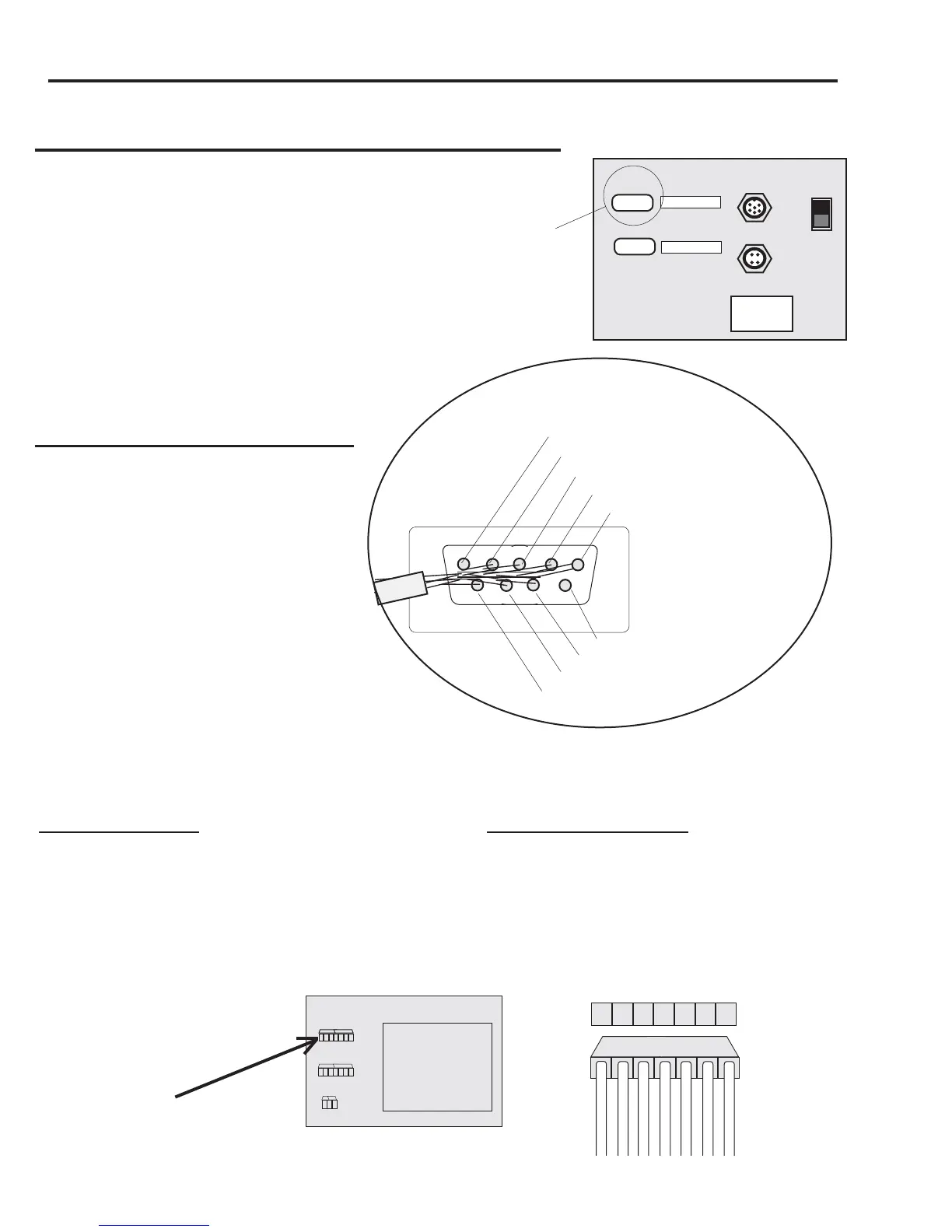
The internal TIREBOSS OCU connections are as follows:
Internal J5 header TIREBOSS DB9 SUB D
Pin 1 (TX) (White/Red wire) Pin 2
Pin 2 (RX) (White/Green wire) Pin 3
Pin 4 (Signal Common) (Black wire) Pin 5
SERVICE MANUAL
TIREBOSS
TM
Tire Pressure Control
WHITE
GREY
PURPLE
BLACK
BLUE
WHITE/GREEN
WHITE/RED
PIN 7
PIN 6
PIN 5
PIN 4
PIN 3
PIN 2
PIN 1
J5
J6
INTERNAL J5 HEADER
Data Logger Connections to TIREBOSS
The Data Logger port is located on the
back of the Operator Control Unit (OCU).
It is a standard DB9 Serial port male connector
and is labelled COM A or DATALOGGER
(has the molded female sockets).
The pin connectors are as follows:
TIREBOSS DB9 SUB D Connections
Pin 1 (no connect)
Pin 2 TX DATA
Pin 3 RX DATA
Pin 4 DTR (not used)
Pin 5 Signal Common (Ground)
Pin 6 DSR (not used)
Pin 7 CTS (not used)
Pin 8 RTS (not used)
Pin 9 (no connect)
POWER/DATA
SPEED/IGNITION
COMM A
COMM B
DATA LOGGER IN-
TERFACE PORT
DATA LOGGER
PROGRAMMING
BACK OF COMM A
(DB9 SUB D)
(view from inside cover)
PIN 5 Signal Common
(Ground)(black)
PIN 4 DTR (not used)(blue)
PIN 3 RX DATA(white/green)
PIN 2 TX DATA(white/red)
PIN 1 (no connect)
PIN 6 DSR (not used)(purple)
PIN 7 CTS (not used)(grey)
PIN 8 RTS (not used)(white)
PIN 9 (no connect)


 To Next Page