NOTE: If vehicle is equipped with only one D2 governor then
the compressor sensing line must be located at the truck wet
tank and the dryers unloader line located at the unloader
port of the compressor D2 governor.
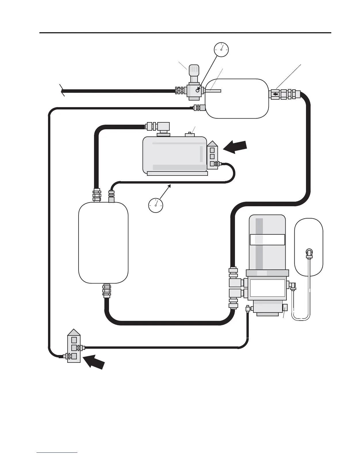
PLUMBING SCHEMATIC
-TRUCK WITH
RECEIVER TANK-
DRYER GOVERNOR SENSING
LINE TO TRUCK WET TANK
1/4 AIRBRAKE TUBE
TRUCK
WET TANK
Internal Standpipe
- mounted inside wet tank
5/8 AIRBRAKE TUBE SUPPLY LINE
Pressure Protection Valve
(Internal Relief Valve)
Adjusted to 100 psi
T
U
RBO-20
0
0
UNLOADER LINE
TO
TIREBOSS
VALVE BOX
PURGE
TANK
PURGE
TANK
UNLOADER LINE
DRYER GOVERNOR
-unload at 125 psi
TRUCK
COMPRESSOR
COMPRESSOR GOVERNOR
-unload at 135 psi
HEATER
250 psi
Safety Relief Valve
One Way
Check Valve
Air Drying
System
-12 TEFLON
with 16.5 cfm
compressor
-16 TEFLON
with 30 cfm
compressor
FACTORY
RECEIVER
TANK
NOTE: Compressor Governor must
be adjusted to 135 psi fi rst, then
adjust Dryer Governor to 125 psi.
(See “Truck Air Compressor Gover-
nor Adjustment” in
Service Manual for details)
5/8 AIRBRAKE TUBE
Install Temporary Gauge
Here to set Dryer Governor
to 125psi
100
Install Temporary
Inline Gauge Here to set
Compressor Governor to
135psi
100
TIREBOSS
TM
Tire Pressure Control
SERVICE MANUAL
1-3
f:tec\manuals\Service\SERVICEv5.indd - V6-0615