TIREBOSS
TM
Tire Pressure Control
SERVICE MANUAL
1-5
f:tec\manuals\Service\SERVICEv5.indd - V6-0615
TIREBOSS
TM
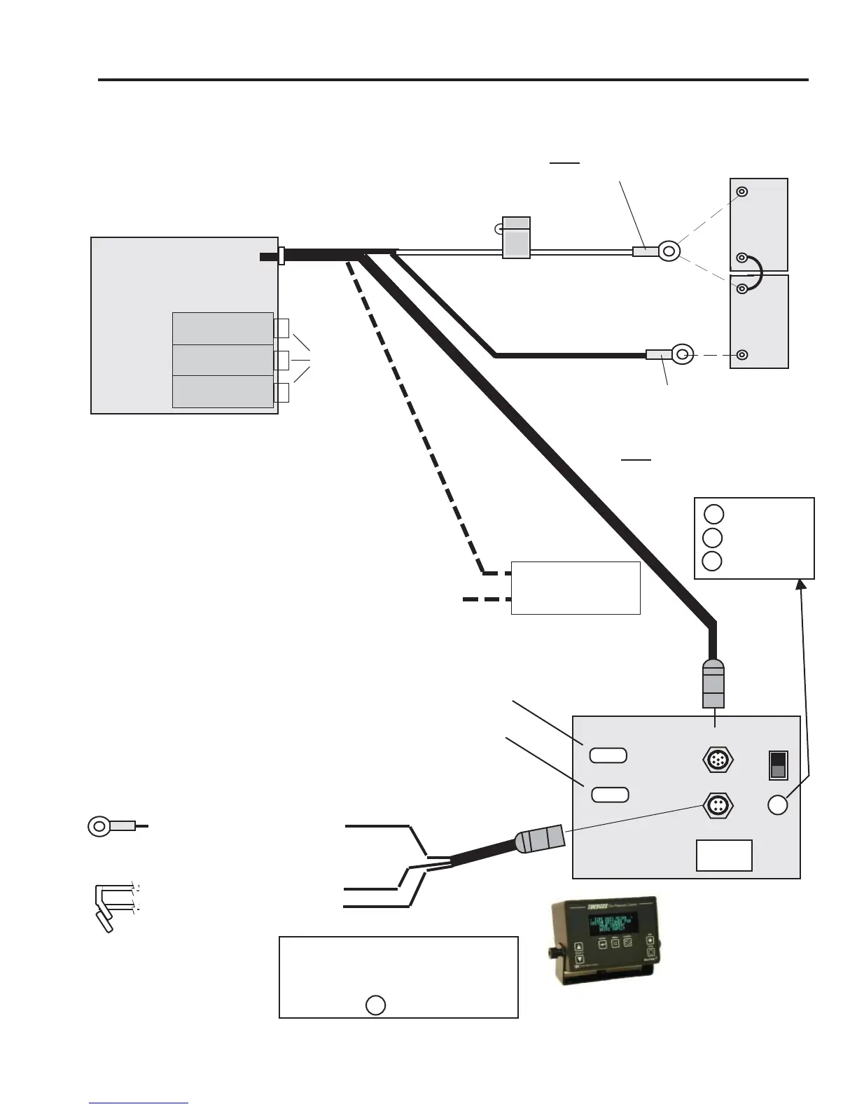
WIRING DIAGRAM
OPERATOR CONTROL CABLE
VALVE PACK BOX
Air Ports
to tires
POWER/DATA
SPEED/IGNITION
COMM A
COMM B
DATA LOGGER IN-
TERFACE PORT
PROGRAM PORT
OPERATOR
CONTROL UNIT
(Cab Mounted)
SPEED SIGNAL
(From Data Link, Impulse
Sender, Frequency Gen-
erator or
Frequency Convertor)
DATA STREAM BUS - (Data Link input)
DATA STREAM BUS
+ (Data Link input)
+12/24V IGNITION SWITCHED ON
(Not Accessory)
12/24V IGNITION SOURCE
Remote Alarm Cable (optional)
Remote Alarm
(optional)
+
-
Ground Connection
GREEN
BLACK
FUSED RED
The ‘switching out’ of
OCUs between trucks is
not recommended as
settings and speed
functions have to be
adjusted per truck
specifi cations.
Fuse holder with
15 amp fuse
White Wire
(Positive)
Black Wire
(Ground)
NOTE - Black Wire to neg.
battery post unless truck has
a Power Disconnect Switch on
ground circuit. Then Black Wire
must be connected to switched
side of master switch.
(24 volt)
(12 volt)
-
+
Truck
Battery
(12 volt)
-
+
Truck
Battery
(12 volt)
(Use 24 volt only if
circuit board, heaters
and controller have
been set for 24 volt
use)
NOTE - White Wire to pos.
battery post unless truck has
a Power Disconnect Switch
on positive circuit. Then White
Wire must be connected
to switched side of master
switch.
G - GPS
J - Data Bus
P - Pulse
Black & Green wires are not
connected on GPS equipped
TIREBOSS systems.
Marked G on rear panel


 To Next Page