i
SERVICE MANUAL
f:tec\manuals\Service\SERVICEv5.indd - V6-0615
TIREBOSS
TM
Tire Pressure Control
SYSTEM DESCRIPTION
The TIREBOSS
TM
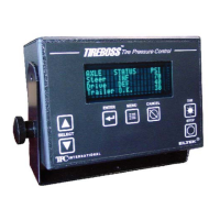
Tire Pressure Control system consists of a computerized Operator Control Unit
(OCU), mounted in the cab, which monitors system activity and displays clear text messages to
the operator of the vehicle. The OCU is linked to a computerized Valve Control Module (VCM) and
pneumatic control valves located outside of the cab. The operator makes simple selections at the
OCU, based on load and speed, which in turn sends messages to the VCM allowing the control
valves to infl ate or defl ate the tire pressures within strict parameters set by the OCU.
The control valves are connected to the tire groups, and individual tire valve stems, through air
lines and various types of rotary couplings mounted at the wheel ends. The air is transferred into
(or out of) the tires through this hardware while the vehicle is moving (See “SYSTEM OVERVIEW”).
The control valves are supplied with air pressure from the vehicle’s air brake system. The air brake
system always has priority over the tire pressure system and is protected by two safety systems.
First a pneumatic pressure protection valve closes air supply to the tire pressure system if brake
tank pressure falls below 95 PSI. An electronic pressure switch that opens the electronic circuit if
the brake tank pressure drops to 75 PSI backs this up. This switch also activates an alert (“LOW
AIR SUPPLY”) on the OCU and electronically prevents any infl ation or defl ation of the tire pressure
system. The system will resume operation once air pressure builds above the safe limits.
Tire pressures are controlled to specifi c set points dependent on vehicle load and speed. Typical
tire pressures change from a maximum of 110 PSI, when fully loaded at highway speeds, down to
27 PSI when empty at reduced off-highway speeds. These pressure ranges are typical for truck
transport vehicles that operate with a standard air supply system and adhere to guidelines set by
the tire manufacturer for automotive applications.
The upper & lower limits for air pressure control are 150 PSI and 10 PSI respectively and are based
on the air supply capacity, pressure transducer limits and application. The control valves can ac-
commodate up to 75 CFM. Tire pressure control & display is accurate within a nominal range of
+/- 2 psi of actual tire pressure. The upper tolerance allows for normal heat buildup in the tires.
All of the operating tolerances are adjustable within the programming software.
The system has various built-in safety features to warn the driver of such things as over-speed
conditions or tire failures. Warnings are both visual and audible (See “SAFETY FEATURES”).