SERVICE MANUAL
TIREBOSS
TM
Tire Pressure Control
3-15
f:tec\manuals\Service\SERVICEv5.indd - V6-0615
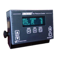
“TRANS RANGE ERROR” ALERT
This alert appears on the operator control unit display to indicate a problem related to the systems transducer.
TROUBLE SHOOTING TRANSDUCERS
1. Compare the air pressure at the Y-strainer schrader valve (located on the side of the valve box) to
the pressure indicated on the operator control unit display. Ensure you are reading the same schrader
valve and controller zone (i.e. drives schrader valve and drives display on controller)
2. If the schrader valve reads 50 psi (example only) and the operator controller reads 0 psi, it means
either the transducer is no longer functioning or it is calibrated incorrectly.
3. You may either change the transducer or attempt to re-calibrate.
RE-CALIBRATING TRANSDUCERS
To recalibrate transducers you will require a multi meter that can read DC volts.
The transducers require approximately 5 volts and are calibrated based on 5 volts which is supplied by the CPU
circuit board. If the supply voltage changes then it could leave the transducers out of range. Once adjusted to that
input voltage then the transducers should begin to function properly.
See schematic on following page
1. Turn all wheel valves off to isolate tires.
2. Inside the TIREBOSS Valve Box, remove cover of Valve Control Module by removing the eight screws.
3. Remove the airline to the transducer at push-to-lock fi tting on side of Valve Control Module.
NOTE: there will be a loss of air from small tank until it is empty
4. Turn on the TIREBOSS system at the operator control unit.
5. Set the multi meter to DC Volts and scale to measure 5 volts.
6. Attach the multi meter BLACK probe to the ground terminal (-VBAT).
7. Touch the multi meter RED probe to the terminal marked “VS”. This is the soldered pin attached to
the transducers red wire. You might need to scrape the solder pin before getting a reading as it has a
protective coating.
8. Record the input voltage reading.
9. Now you need to get an accurate output voltage reading from the transducer. With the BLACK probe
still attached to the “(-VBAT)” terminal, touch the red probe to the terminal marked “OUT” on the
transducer (which is connected to the green transducer wire)
10. Record the output voltage reading.
Now compare the readings you have recorded to the chart on the following pages. Find your recorded input volt-
age on the chart. If the output voltage on the chart differs from what your readings are, (more than +/- 0.005V) you
will have to calibrate the transducer. To calibrate the transducer, locate the adjusting screw and turn until the multi
meter reads the correct output voltage as on the chart. (NOTE: you may have to remove sealant from the end
of the adjusting screw, once you have completed the calibration, replace a small amount of silicone on
adjusting screw to ensure it stays at desired position).