SERVICE MANUAL
TIREBOSS
TM
Tire Pressure Control
3-7
f:tec\manuals\Service\SERVICEv5.indd - V6-0615
PAD or TEMP SENSOR wiring is not polarity sensitive (can be connected either way). The TEMP SENSOR will
call for the heaters to be turned on only when the sensed temperature is +3 Degrees C (+38 Degrees F) or lower.
Note that a “Heater Current Error” alert will not be caused by a defective TEMP SENSOR or its related wiring.
Any problem related to the TEMP SENSOR or its circuit will cause a “Temp Sensor Error” alert to appear on the
operator control screen.
Trouble shooting a Heater Current Error fault:
Perform the following trouble shooting steps in the order listed to isolate the cause of the fault.
1. Check to ensure that the main Power and Ground wire connections to the heaters at terminals HT-COM
and 28V OR 14V are tight.
2. Using a multi-meter, connect the negative lead at the -VBAT terminal and check to ensure there is
voltage present on both sides of Fuse F2 (11-15V on a 12 volt system, 22-30V on a 24 volt system).
3. With the Cab Controller on and the TEMP SENSOR activated, again using a multi-meter with the
negative lead connected at the -VBAT terminal, check to ensure there is 11-15V (22-30V) present at
terminal HT-COM.
Note: Activating the TEMP SENSOR can be accomplished by either performing the test in an environment where
the ambient temperature is below +3 degrees C (+38 degrees F) or by spraying the TEMP SENSOR using
an aerosol spray freeze solution.
4. Check and ensure that the correct numbers of heaters are installed (1 for each valve).
5. Check for the correct heater circuit resistance. Note that this must be performed with the controller shut
off (to ensure that there is no power present at the heaters). Remove the heater wires from Terminal
Strip J2 at locations HT-COM and 28V OR 14V and, using a multi-meter set to measure resistance,
connect one of the multi-meter leads to each heater wire. The resistance in Ohms, for the corresponding
number of heaters, should be within +/- .2 Ohm of the values listed in the following table. Note that all
heaters are connected together to a common pair of wires going to the valve board (HT-COM and 28V
OR 14V).
If only 1 heater is in the circuit and the measured resistance is outside of the acceptable range, replace
the heater. If more than 1 heater is in the circuit, then separate the heaters and check each individual
heater to determine which one is faulty.
6. Check the VB program in the operator controller for the correct heater settings. For example, heaters
are either unchecked on user page or have a different quantity listed than the number of valves in the
system. This can only be checked by TPC or their certifi ed installers.
7. Check the VB program in the operator controller to ensure the correct heater wattage is indicated in the
protected parameters. For example, are the heaters 40 watt rather than 30 watt? This can only be
checked by TPC or their certifi ed installers.
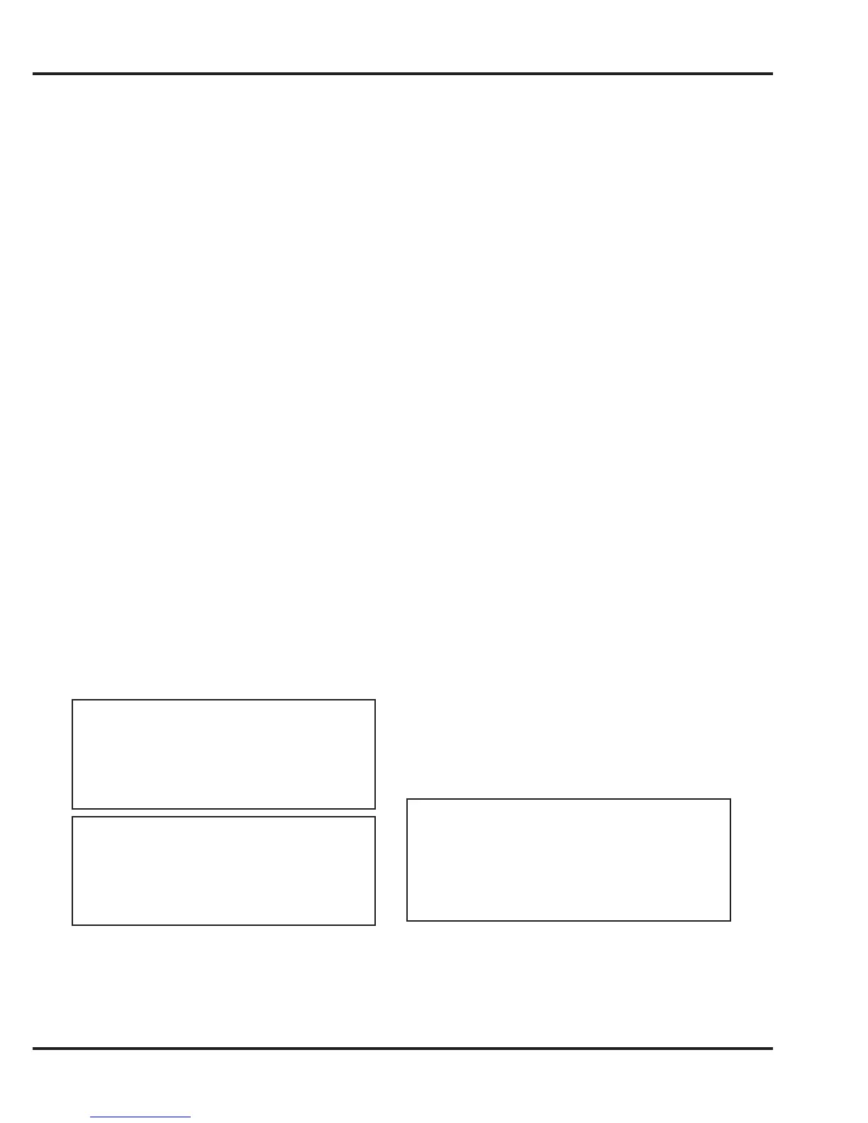
12V – 40W HEATERS
Ideal Acceptable
Range
1 heater – 3.6 Ohms – 3.8 Ohms / 3.4 Ohms
2 heaters – 1.8 Ohms – 2.0 Ohms / 1.6 Ohms
3 heaters – 1.2 Ohms – 1.4 Ohms / 1.0 Ohms
24V – 40W HEATERS
Ideal Acceptable
Range
1 heater – 14.4 Ohms – 14.6 Ohms / 14.2
Ohms
2 heaters – 7.2 Ohms – 7.4 Ohms / 7.0 Ohms
3 heaters – 4.8 Ohms – 5.0 Ohms / 4.6 Ohms
12V – 30W HEATERS
Ideal Acceptable
Range
1 heater – 4.8 Ohms – 5.0 Ohms / 4.6 Ohms
2 heaters – 2.4 Ohms – 2.6 Ohms / 2.2 Ohms
3 heaters – 1.6 Ohms – 1.8 Ohms / 1.4 Ohms