3-10
f:tec\manuals\Service\SERVICEv5.indd - V6-0615
SERVICE MANUAL
TIREBOSS
TM
Tire Pressure Control
2. On the Valve Controller board, check if LED light (L1) is On or Off.
Using a multi-meter, set to DC volts, connect the negative lead at the –VBAT terminal.
- If L1 is On, determine if voltage is present at terminal VPS.
- If voltage is present at terminal VPS, proceed to step 5.
3. If L1 is Off, determine if voltage is present at terminal VPS.
- If voltage is not present at terminal VPS, determine if voltage is present at terminal RLY.
- If voltage is not present at terminal RLY then proceed to step 6.
4. If voltage is present at RLY but not at VPS, check to determine if voltage is present at both terminals of fuse
F9. Note: Fuse F9 is located between Terminal strips J2 and J7. Fuse F9 is the fuse closest to the lower
edge of the circuit board.
- If voltage is not present at one of the fuse terminals, using your fi nger, lightly touch the fuse body to
determine if it is hot. If the fuse body is hot, then a short to ground exists somewhere along the VPS wire
between the Valve Controller and the Cab Controller.
- If voltage is not present at either terminal of fuse F9, then either replace relay 1CR on the Valve
Controller circuit board or replace the Valve Controller circuit board.
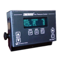
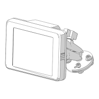
5. Remove the rear cover of the Cab Controller leaving the unit turned On with all electrical connectors in place.
Using a multi-meter, set to DC volts, connect the negative lead at J1-terminal 2 (black) wire. Using the
positive multi-meter lead, determine if there is voltage present at the Power/Data circular 6 pin connector (on
inside of rear cover) where the VPS (Green) wire terminates.
- If voltage is not present, fi rst check for continuity on the Green wire through the connector on the rear cover.
If no continuity through the two piece connector, remove the cable end and check continuity through the rear
cover connector. If this is OK, it could be a loose connection at the pin connectors where they join. Using a
seal pick, slightly close the split barrel female socket in the cable end connector and try again. If problem
persists, replace either the rear cover connector or cable end connector. Secondly, if the connectors are OK,
check for continuity on the green wire through the Power/Data cable. If no continuity through the cable, repair
or replace the cable.
- If voltage is present at the circular connector, then determine if voltage is present at connector J1-terminal 3
(green) wire on the cab controller circuit board. If voltage is not present, either repair or replace the Power/
Data connector sub-assembly (internal wire harness assembly). If voltage is present, then replace the Cab
Controller or the Cab Controller circuit board.
6. Remove the rear cover of the Cab Controller leaving the unit turned On with all electrical connectors in place.
Using a multi-meter, set to DC volts, connect the negative lead at J1-terminal 2 (black) wire. Using the
positive multi-meter lead, determine if there is voltage present at the Power/Data board connector, J1-terminal
4 (Orange) wire.
- If voltage is not present at pin 4 on the J1 connector, then replace the Cab Controller or Cab Controller ircuit
board.
- If voltage is present at this point, then move to the rear cover circular 6 pin connector and determine if
voltage is present at the terminal where the RLY (Orange) wire terminates.
- If voltage is present at this location, fi rst check for continuity on the Orange wire through the connector on
the rear cover. If no continuity through the two piece connector, remove the cable end and check continuity
through the rear cover connector. If this is OK, it could be a loose connection at the pin connectors where
they join. Using a seal pick, slightly close the split barrel female socket in the cable end connector and try
again. If problem persists, replace either the rear cover connector or cable end connector. Secondly, if the
connectors are OK, check for continuity on the orange wire through the Power/Data cable. If no continuity
through the cable, either repair or replace the cable.