Assembly Instructions | ILM Servo Kits
18 Edition 03/2021 EN
Reference design for ILM servo kits
6 REFERENCE DESIGN FOR ILM SERVO KITS
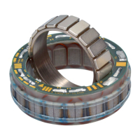
Fig. 10 shows a reference design with installation notes for integrating the ILM servo kit.
The design specifications for the specific type of ILM servo kit are contained in the
“Drawing ILM XXxXX” drawings which are available on our website. Joining of the rotor
and shaft or stator and housing can also be carried out by TQ-Drives, if required.
Stator
Rotor shell with
magnets
Hollow or solid shaft,
concentricity and
radial runout 0.02 mm
Bonding rotor
and shaft
Bonding the stator with
thermally-conductive
adhesive
Adhesive injection hole,
Ø 0.9 mm
Leave 8 to 10 mm
clearance for wiring
Be aware of the
effect of the
motor’s magnetic
field on encoders
with magnetic code
wheels.
Design specifications
as shown in the
"MEBS XX-YY Installation“
drawing
Keep this area clear to prevent
magnetic eddy current losses
Fig. 10: Reference design for ILM servo kits
 Loading...