Montage [Mounting]
TR-Electronic GmbH 2007, All Rights Reserved Printed in the Federal Republic of Germany
Page 34 of 36 TR - ELA - BA - DGB - 0004 - 03 08/05/2011
5 Montage [Mounting]
Bei der Montage des TR-Linear-Wegmess-Systems ist
darauf zu achten, dass keine starken magnetischen und
elektrischen Störfelder im Bereich des Sensors auftreten.
Unzulässige Störfelder können die Messgenauigkeit
beeinflussen. Im Bereich des Mess-Stabes darf die
Feldstärke max. 3 mT betragen.
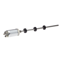
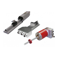
Mechanik Rohr-Gehäuseausführung
Der Messwert wird berührungslos über das Magnetfeld des
Positionssensors auf den Sensorstab eingekoppelt. Die
Präzision der Messwerte ist u.a. abhängig von der
Symmetrie der Magnetfeldgeometrie. Das bedeutet für die
Mechanik, dass der Positionssensor zum Rohr zentrisch
angebaut, und axial parallel präzise zu führen ist.
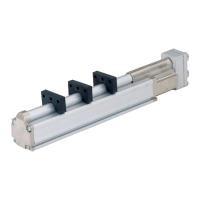
Mechanik Profil- Gehäuseausführung
Der Einbau des Wegsensors ist relativ einfach, da die
mechanische Führung des Positionssensors entfällt. Die
optimalen Gleiteigenschaften des Mess-Schlittens ergänzen
sich mit dem berührungslosen Abtasten der Messposition.
Zur Vermeidung von zusätzlichem Verschleiß der
Gleitführungen am Mess-Schlitten müssen die
Toleranzangaben (Winkel- und Parallelversatz) eingehalten
werden.
Die Präzision der Messwerte ist u.a. abhängig von der
Symmetrie der Magnetfeldgeometrie. Das bedeutet beim
Profil-System ohne Mess-Schlitten, dass der
Positionssensor zum Mess-System präzise, axial und in der
Höhe parallel zu führen ist. Der max. Abstand von 4 mm
zwischen dem Positionssensor und dem Profilgehäuse darf
dabei nicht überschritten werden.
Before mounting TR-linear-Transducer, make sure there are
no strong magnetic and electric interference fields in the
vicinity.
Inadmissible interference fields can influence the measuring
precision. The field strength may be max. 3 mT in the
vicinity of the measuring rod.
Mechanics rod housing design
The measurement is one coupled contactlessly about the
magnetic field of the position sensor on the sensor rod. The
precision of the measurements is among others addicted to
the balance of magnetic field geometry. This means for the
mechanics, that the position sensor has to be led centrically
add-only and axially parallel to the rod precisely.
Mechanics profile- housing design
Since the position sensor by the measuring body
mechanically one leads, is relatively simple the installation
the TR-linear-Transducer system.
The exact guidance of the captive-sliding magnet and non-
contact and wear free measurement system each other
optimally. In order to reduce the wear between captive-
sliding magnet and measuring body to a minimum, the
dimensional tolerances for angle and parallel disalignment
must be absolutely kept.
The exact of the measured value depends also on the
symmetry of magnetic field geometry. If no captive-sliding
magnet is used, the position sensor must be led exactly
in axial direction to the measuring body. The distance from
maximally 4mm between position sensor and measuring
body may not be exceeded.
 Loading...