BAS-SVX44A-EN 11
Installation and Wiring
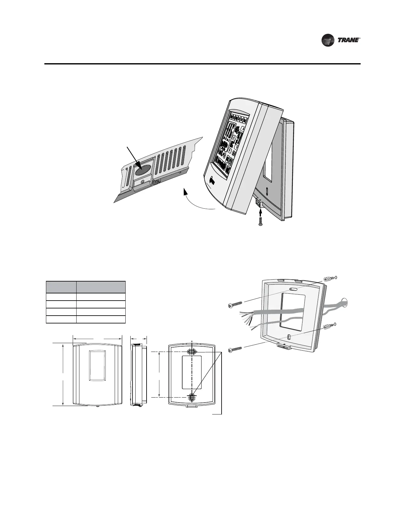
Figure 1. Security screw removal and cover release
2. Push the cover thumb tab to release the cover from the backplate as shown above.
3. Route the wires through the opening in the backplate as shown below. Wires should be marked
to
ensure proper connection to terminals.
Figure 2. Wire routing, mounting, and mounting dimensions
4. If mounting the backplate directly to a wall surface, hold the backplate against the surface and
then
level and mark the fastener locations.
5. Secure the backplate using appropriate fasteners (refer to the section, “Mounting Surfaces,”
p. 8.) The thermostat must be level and plumb to ensure proper air movement through the
thermostat enclosure.
Security Screw
NOTE: If the
security screw is
installed, remove
it before
attempting to
remove the cover.
Cover thumb tab
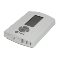
Dimension
Programmable
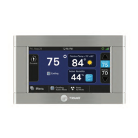
Touch-screen
H 3.3 in. (85 mm)
W 5.9 in. (150 mm)
D 1.3 in. (33 mm)
M 3.3 in. (85 mm)
W
H
D
M
Two (2) slots for standard #8-32 (M4),
2”x4” junction box mounting screws.