12 BAS-SVX44A-EN
Installation and Wiring
Wiring and Wiring Diagrams
Wiring
WARNING
Hazardous voltage!
Disconnect all electric power, including remote disconnects before servicing. Follow proper
lockout/tagout procedures to ensure the power cannot be inadvertently energized. Failure to
disconnect power before servicing could result in death or serious injury.
NOTICE
Equipment damage!
Applying excessive voltage to the thermostat can permanently damage it.
Note: Terminal
blocks are included with the mounting hardware contained in a small plastic bag
(new installation) or remove terminal blocks from pin header (existing installation).
To wire the thermostat:
1. Connect the wires to the terminal block(s) by:
a. Removing approximately 1/4 inch (6 mm) of insulation from the wires.
b. Using the terminal block screws to securely fasten each wire into the terminal block.
Note: Refer
to Table 3, p. 13 and the wiring diagrams on page 14- through 18 to
determine the correct terminal for each wire.
In some cases the terminal labels (such as Y, G, or R) correctly correspond to the
first
letter of the color wire in which they are connected. However, it is important to
verify which equipment terminals are connected at the other ends of the wires
before connecting the wires to the thermostat.
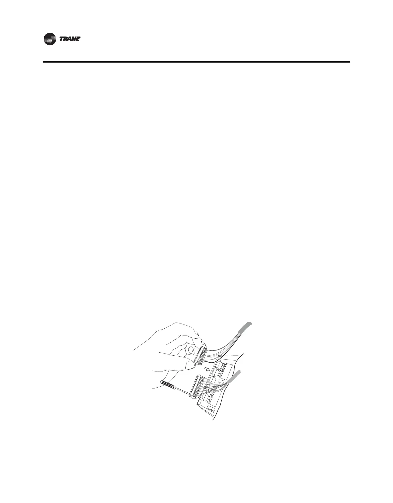
2. Align the pins/label on the circuit board with the holes/label on the terminal blocks and gently
push
the wired terminal blocks into place on the circuit board (refer to Figure 3).
Figure 3. Attaching the wired terminal blocks to the pins on the circuit boards
3. Push the excess wire through the hole in the wall cavity or into the junction box.
Important: Do not coil excess wire between the thermostat and the backplate. Use non-
flammable insulation to prevent air movement between the wall cavity and the
thermostat.
(W1)W2
Y2
S1
S2
Hp
Hs
Dh
A
C
G
(O/B)W
Rc
R
Y
C G Y W Rc R
W2 Y2 A S1 S2 Hp Hs Dh