BAS-SVX44A-EN 13
Installation and Wiring
Terminal Identification
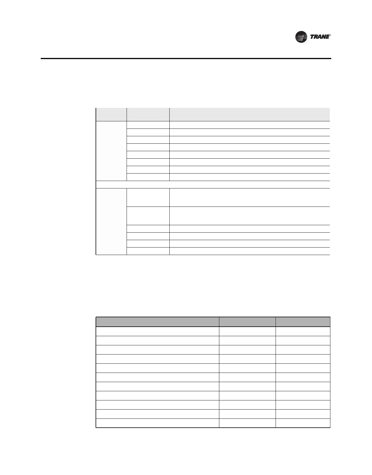
Table 3 identifies the programmable thermostat terminals.
Wiring Diagrams
The following diagrams show typical wiring scenarios for the touch-screen programmable
thermostat.
Use Table 4 and the corresponding figure to correctly wire the thermostat.
Table 3. Terminal identification
Connector
Type
Terminal
Label
(a)
(a) Label order above is how they appear on the thermostat terminal block.
Terminal Description
8-pin Connectors
Dh Dehumidify relay
Hs External humidity sensor input
Hp External humidity sensor power
S2 External temperature sensor
S1 External temperature sensor
A Economizer relay
Y2 Stage 2 compressor control relay
(W1)W2 (Aux or Em heat relay)
(b)
Second stage heat relay
(b) Text in parentheses applies to only heat pump systems.
6-pin connectors
R
24 Vac heating
Important: Terminal shipped with jumper connected. Remove jumper if the 24 Vac
power supplies are separate.
Rc
24 Vac cooling
Important: Terminal shipped with jumper connected. Remove jumper if the 24 Vac
power supplies are separate.
(O/B)W (Changeover valve)
(b)
Heat relay
Y Stage 1 compressor control relay
G Fan relay
C Common
Table 4. System type options for programmable thermostats
System Type Value for Option 130
See Diagram
1-heat/1-cool, conventional 1 Figure 4
1-heat/1-cool, heat pump without auxiliary heat 2 Figure 5
1-heat only, conventional without fan 3 Figure 6
1-heat only, conventional with fan 4 Figure 7
1-cool, conventional 5 Figure 8
2-heat/1-cool, heat pump with auxiliary heat 6 Figure 9
2-heat/2-cool, conventional 7 Figure 10
2-heat/1-cool, conventional 8 Figure 11
1-heat/2-cool, conventional 9 Figure 12
2-heat/2-cool, heat pump without auxiliary heat 10 Figure 13
3-heat/2-cool, heat pump with auxiliary heat 11 Figure 14