Installation
SO-SVN038A-EN 17
Installation of Options
LON Option
The Symbio™ 800 system will use a U60 LON module through
the USB connection instead of the LCI-C LLID.
1. Install the U60 LON module (MOD02977) on the DIN rail
on the door. Put it at the left side of Symbio 800.
2. Connect the U60 LON module to the Symbio 800 by a USB
cable (provided by the module). This cable can connect to
any of the four USB ports under the Symbio 800 controller.
3. Connect the U60 LON module to the BAS by shield cable
and terminal. The terminal is provided by the module.
LON wiring, ref. 50712795, 50712799, 50712802, 50712805
or 50712806 depend on different unit. For details, see Table 3,
p. 28.
Communication Option
Symbio 800 system supports up to 3 wireless interfaces at
same time, these are,
• Wi-Fi mobile APP for BAS interface
• Air-Fi BACnet via Zigbee for component interface
• LTE 4G modem interface for remote communications.
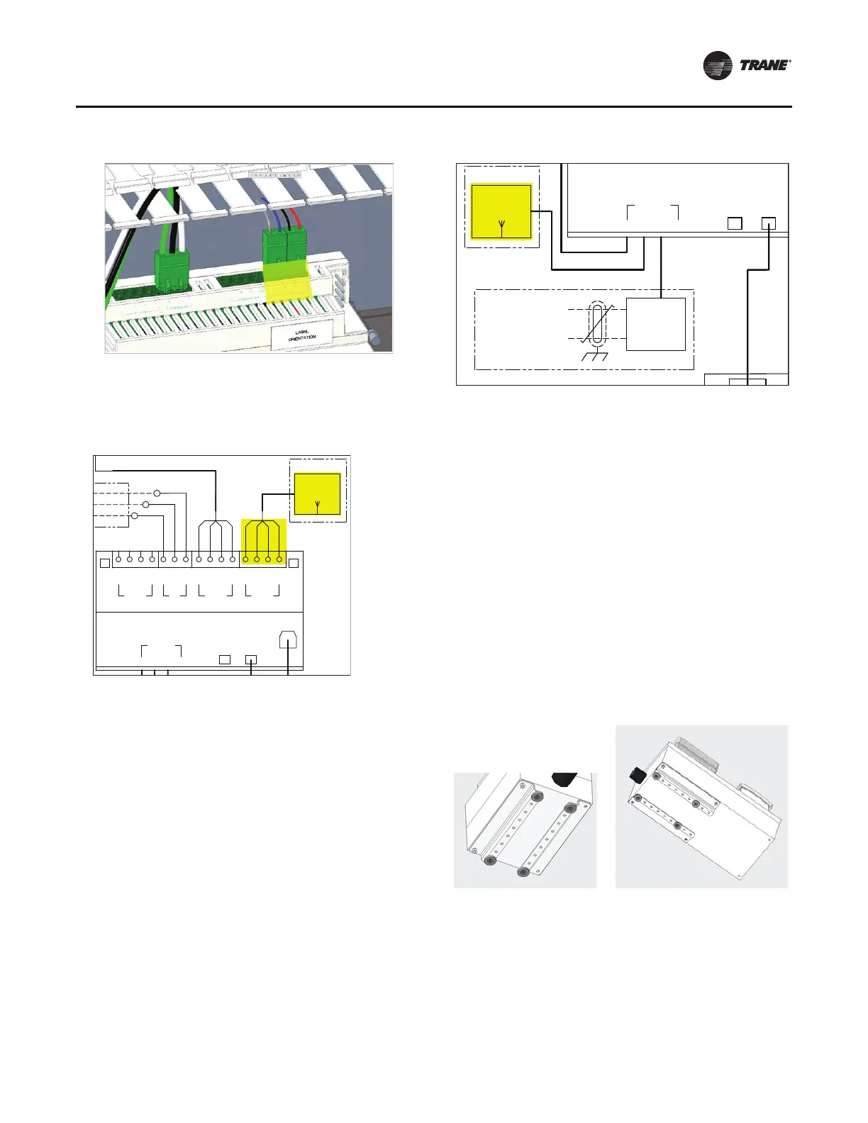
Wi-Fi Installation
Refer to BAS-SVN042*-EN for more information. Mounting
and wiring of Wi-Fi module (MOD03122).
1. Drill a 1.36-inch hole on the top of polycarbonate box.
2. Securely fasten the Wi-Fi module by gasket and nut which
provided with the module.
3. Connect the Wi-Fi module to Symbio™ 800 by a USB
cable.
4. Plug the USB MICRO-B side to the bottom of the Wi-Fi
module and USB-A side to any one of the four USB ports
under the Symbio 800 controller.
Note: Wi-Fi wiring, ref. 50712795, 50712799, 50712802,
50712805 or 50712806 depend on different unit. For
details, see Table 3, p. 28.
Air-Fi Installation
Refer to BAS-SVX040*-EN for more information. Mounting
and wiring of Air-Fi module (0185-0424-0100).
1. Drill 0.87-inch hole on the top of polycarbonate box and
align this hole with thread hole on the module.
2. Securely fasten the Air-Fi® module with a M4 screw.
3. Connect the Air-Fi module to Symbio™ 800 with a
Modbus® cable.
4. Remove the cover of the module, connect 4 wires cable
into 4 hosing connector and plug in the Air-Fi module.
5. .Connect other side of the cable into two hosing connector
and plug in the IMC terminal on the Symbio 800 controller.
Figure 15. LON
Figure 16. LON wiring
1A22 SYMBIO 800 UNIT CONTROLLER
ETHERNET
12
USB
1324
LON
1K47
INTERFACE
TRACER
OPTIONAL
COMMUNICATIONS
LTE
4Y2
MODEM
OPTIONAL
Figure 17. Wi-Fi wiring
+24
G
-
+
IMC
RED
BLK
GRN
WHT
RED
BLK
BLU
GRY
VDC
+24
G
-
+
MACHINEBUS
VDC
P3
-
+
BACKNET
P1
-
+
-
+
MODBUS
P2
G
IMC
B
IMC
A
1A22 SYMBIO 800 UNIT CONTROLLER
SERVICE
ETHERNET
12
USB
1324
TOOL
WI-FI
4Y1
ANTENNA
OPTIONAL
USB1
LTE
4Y2
MODEM
OPTIONAL
WHT
GRN
BLK