Installation
22 SO-SVN038A-EN
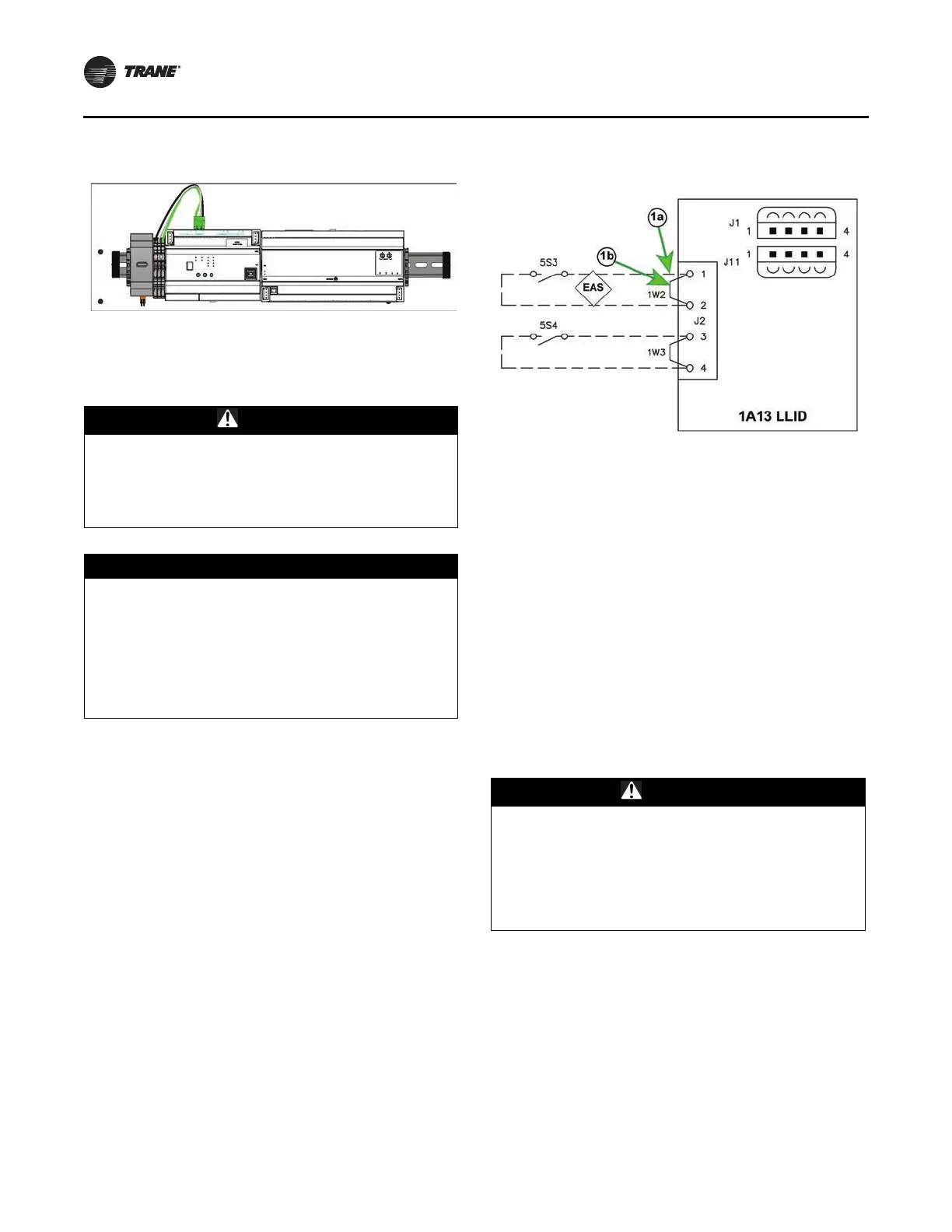
The communications wiring will be terminated at the Modbus
distribution terminal (1X3) beside Symbio 800 using the three
poles connector which provide in energy meter kits.
480 Volts and Lower Installations
• POTENTIAL INPUT – Install provided fused inputs to line
voltage per schematic.
• CURRENT INPUT – Install provided Rogowski CTs per
schematic.
Expansion Module Option
CDUB retrofit panel reserve place of expansion module beside
Symbio™ 800 controller.
• There are few configurations that depend on I/O
requirements and din rail length.
• Din rail in the CDUB panel space is 13.9-inches. One XM32
or two XM30 can be added.
• If XM70 is selected, a 20-inch din rail is required, in
0185-3495-0100. For detailed I/O information, see
50712794.
Note: This option is only applied for CDUA, CVRE
aftermarket retrofit panel.
Figure 34. Modbus distribution terminal
Figure 35. Communication wiring, ref. 50712792
Figure 36. 480V energy meter wiring, ref. 50712756
Figure 37. XM32 expansion module mounting
2T50
2T51
2T52
LINE 99
TO 1X3
WHT
BLK
WHT
BL
K
WH
T
BL
K
RE
D
BL
K
BL
U
YEL
ORG
BRN
WHT
2F54
2F52
2F53
0.5A
0.5A
0.5A
DETAIL A
ENERGY METER OPTION
NOT USED
WB22
X1 X2 X1 X2 X1 X2 +-G
MODBUS
VOLT INPUTS
L1 L2 L3 N
2F1 LINE SI DE
2F2 LINE SI DE
2F3 LINE SI DE
2P25
ENERGY METER
(E23)
CT INPUTS
L1 L2 L3
T
T
T
T
T
T
T
T
T