154
RT-SVX073A-EN
Important: COMPRESSOR SERVICE VALVES MUST BE
FULLY OPENED BEFORE STARTUP
(SUCTION, DISCHARGE, AND LIQUID
LINE).
3. Close the disconnect switch or circuit protector switch
that provides the supply power to the unit terminal block
or the unit mounted disconnect switch to allow the
crankcase heater to operate a minimum of 8 hours
before continuing.
4. Turn the 115 volt control circuit switch and the 24 volt
control circuit switch to the “On” position.
Important: Compressor Damage could occur if the
crankcase heater is not allowed to operate
the minimum of 8 hours before starting the
compressor(s).
5. Open the access door located in the unit control panel,
and press Manual Overrides to display the first service
screen. Refer to the latest edition of the applications
programming guide (RT-SVP07*-EN) for applications
for the Manual Overrides screens and programming
instructions.
6. Use tables in “Voltage Imbalance,” p. 93 to program the
following system components for operation by scrolling
through the displays.
7. Attach a set of service gauges onto the suction and
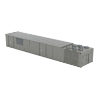
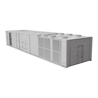
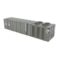
discharge gauge ports for each circuit. See Figure
104, p. 155 for the various compressor locations.
WARNING
Rotating Components!
Failure to disconnect power before servicing could
result in rotating components cutting and slashing
technician which could result in death or serious
injury.
During installation, testing, servicing and
troubleshooting of this product it may be necessary
to work with live and exposed rotating components.
Have a qualified or licensed service individual who
has been properly trained in handling exposed
rotating components, perform these tasks.
8. Press the Auto key to start the test. Remember that the
delay designated in step 8 must elapse before the
system will begin to operate.
9. Once each compressor or compressor pair has started,
verify that the rotation is correct. If a scroll compressor
is rotating backwards, it will not pump and a loud
rattling sound can be observed. Check the electrical
phasing at the load side of the compressor contactor. If
the phasing is correct, before condemning the
compressor, interchange any two leads to check the
internal motor phasing. If the compressor runs
backward for an extended period (15 to 30 minutes),
the motor winding can over heat and cause the motor
winding thermostats to open. This will cause a
“compressor trip” diagnostic and stop the compressor.
10. Press the STOP key and clear all Manual Overrides in
the unit control panel to stop the compressor operation.
11. Repeat steps 5–11 for each compressor stage and the
appropriate condenser fans.
Refrigerant Charging
1. Attach a set of service gauges onto the suction and
discharge gauge ports for each circuit. See Figure
104, p. 155 for the various compressor locations.
2. Open the access door, located in the unit control panel,
and press the Manual Overrides key to display the first
service screen. Refer to the latest edition of the
applications programming guide for VAV applications
for the Manual Overrides screens and programming
instructions.
3. Use tables in “Voltage Imbalance,” p. 93 to program the
following system components for the number 1
refrigeration circuit by scrolling through the displays;
VFD (100%, if applicable)
OCC/UNOCC Relay (Unoccupied for VAV units)
All Compressors for each circuit (On)
Condenser Fans for each circuit (On)
WARNING
Rotating Components!
Failure to disconnect power before servicing could
result in rotating components cutting and slashing
technician which could result in death or serious
injury.
Disconnect all electric power, including remote
disconnects before servicing. Follow proper lockout/
tagout procedures to ensure the power can not be
inadvertently energized.
4. Press the Auto Button key to start the test. Remember
that the delay designated in step 4 must elapse before
the system will begin to operate.
5. After all of the compressors and condenser fans for the
number 1 circuit have been operating for approximately
30 minutes, observe the operating pressures. Use the
appropriate pressure curve found in “(60 Hz) Air-
Cooled Condensers,” p. 110 or “(50 Hz) Air-Cooled
Condensers,” p. 124 to determine the proper operating
pressures. For superheat and subcooling guidelines,
refer to “ Expansion Valves,” p. 158.
Important: Do Not release refrigerant to the
atmosphere! If adding or removing
refrigerant is required, the service
technician must comply with all Federal,
State and local laws.
6. Verify that the oil level in each compressor is correct.
The oil level may be down to the bottom of the
sightglass but should never be above the sightglass.
7. Press the STOP key and clear all Manual Overrides in
the unit control panel to stop the system operation.
Unit Startup

 Loading...


