RT-SVX073A-EN
47
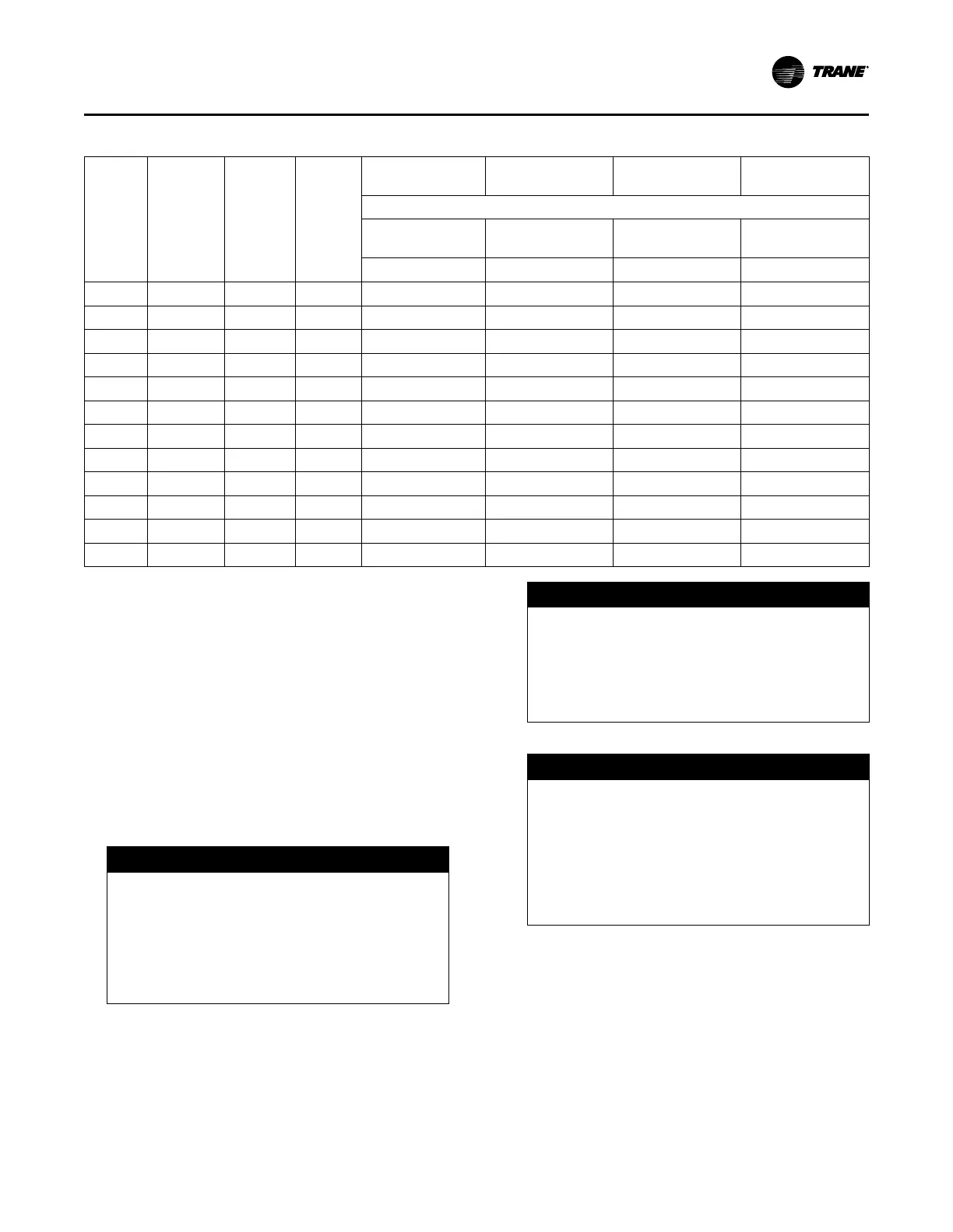
Table 17. Gas heat piping penetration measurements
Tons
Energy
Recovery
Wheel
(ERW)
Pieces
Heat
(MBH)
Gas Flue
Condensate Drain
Outlet
Gas Connection,
Horizontal
Gas Connection,
Base
Horizontal Distance
Mist Elim to Flue C/
L Unit End to Hole C/L Unit End to Hole C/L
K C H B
90-105 No ERW 1 & 2 Pc 1800 160 1/16 254 14/16 266 4/16 274 11/16
90-105 No ERW 1 & 2 Pc 1100 159 15/16 263 15/16 265 5/16 274 11/16
90-105 No ERW 1 & 2 Pc 850 159 15/16 263 15/16 265 5/16 274 11/16
120-150 No ERW 1 & 2 Pc 2500 214 11/16 321 337 7/16 339 7/16
120-150 No ERW 1 & 2 Pc 1800 214 13/16 319 11/16 331 339 7/16
120-150 No ERW 1 & 2 Pc 1100 214 11/16 327 14/16 330 1/16 339 7/16
90-105 ERW 1 & 2 Pc 1800 164 11/16 351 5/16 362 10/16 371 1/16
90-105 ERW 1 & 2 Pc 1100 164 8/16 360 6/16 361 12/16 371 1/16
90-105 ERW 1 & 2 Pc 850 164 8/16 360 6/16 361 12/16 371 1/16
120-150 ERW 1 & 2 Pc 2500 219 13/16 417 7/16 433 14/16 435 14/16
120-150 ERW 1 & 2 Pc 1800 220 416 2/16 427 7/16 435 14/16
120-150 ERW 1 & 2 Pc 1100 219 13/16 424 5/16 426 8/16 435 14/16
General Coil Piping and Connection
Recommendations
Proper installation, piping, and trapping is necessary to
ensure satisfactory coil operation and to prevent
operational damage:
Note: The contractor is responsible for supplying the
installation hardware.
☐ Support all piping independently of the coils.
☐ Provide swing joints or flexible fittings on all
connections that are adjacent to heating coils to absorb
thermal expansion and contraction strains.
☐ Install factory supplied control valves (valves ship
separately).
NOTICE
Connection Leaks!
Failure to follow instructions below could result in
damage to the coil header and cause connection
leaks.
Use a backup wrench when attaching piping to
coils with copper headers. Do not use brass
connectors because they distort easily.
☐ When attaching the piping to the coil header, make the
connection only tight enough to prevent leaks.
Maximum recommended torque is 200 foot-pounds.
NOTICE
Over Tightening!
Failure to follow instructions below could result in
damage to the coil header.
Do not use teflon-based products for any field
connections because their high lubricity could
allow connections to be over tightened.
☐ Use pipe sealer on all thread connections.
NOTICE
Leakage!
Failure to follow instructions below could result in
equipment damage.
Properly seal all penetrations in unit casing from
inner to outer panel in order to prevent
unconditioned air from entering the module, as
well as prevent water from infiltrating the
insulation.
☐ After completing the piping connections, seal around
pipe from inner panel to outer panel.
Hot Water Heat Units (SLH_)
Hot water heating coils are factory installed inside the
heater section of the unit. Once the unit is set into place,
the hot water piping and the factory provided 3–way
modulating valve must be installed. The valve can be
installed inside the heat section or near the unit. If the valve
is installed in a remote location, use field supplied wiring to
extend the control wires from the heater section to the
valve. Two access holes are provided in the unit base as
Installation