50
RT-SVX073A-EN
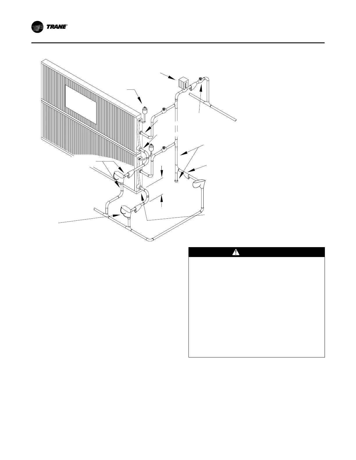
Figure 33. Steam coil piping
2-Way
Modulating
Valve
Vacuum
Breaker
(2 locations)
Steam
Main
IN
(2 locations)
OUT
(2 locations)
Return
Main
T
y
p
e
NS
S
tea
m
Coils
(A
R
I
Lis
ted)
Use same size pipe
as Trap Connections
(3 locations)
Steam Trap
(Float & Thermostatic Type)
(3 locations)
Gate Valve
(3 locations)
Use same size pipe
as Steam Main
Use same size pipe
as Coil Connection
(2 locations)
Strainer
(3 locations)
12” Minimum
(both outlets)
Disconnect Switch with External Handle
Units come equipped with a factory mounted disconnect
switch with an externally mounted handle. This allows the
operator to disconnect power from the unit without having
to open the control panel door. The handle has three
positions:
• “ON” - Indicates that the disconnect switch is closed,
allowing the main power supply to be applied at the
unit.
• “OFF” - Indicates that the disconnect switch is open,
interrupting the main power supply to the unit controls.
• “RESET/LOCK” - Turning the handle to this position
resets or disconnects the device. To disconnect, the
handle must be turned to the Reset/Lock position.
Pulling the spring-loaded thumb key out, so the lock
shackle can be placed between the handle and the
thumb key, locks the handle so the unit cannot be
energized.
WARNING
Hazardous Voltage w/Capacitors!
Failure to disconnect power and discharge capacitors
before servicing could result in death or serious
injury.
Disconnect all electric power, including remote
disconnects and discharge all motor start/run
capacitors before servicing. Follow proper lockout/
tagout procedures to ensure the power cannot be
inadvertently energized. For variable frequency drives
or other energy storing components provided by
Trane or others, refer to the appropriate
manufacturer’s literature for allowable waiting periods
for discharge of capacitors. Verify with a CAT III or IV
voltmeter rated per NFPA 70E that all capacitors have
discharged.
The handle can be locked in the “OFF” position by
completing the following steps (see Figure 34, p. 51):
1. While holding the handle in the “OFF” position, push
the spring loaded thumb key, attached to the handle,
into the base slot.
2. Place the lock shackle between the handle and the
thumb key. This will prevent it from springing out of
position.
Installation