52
RT-SVX073A-EN
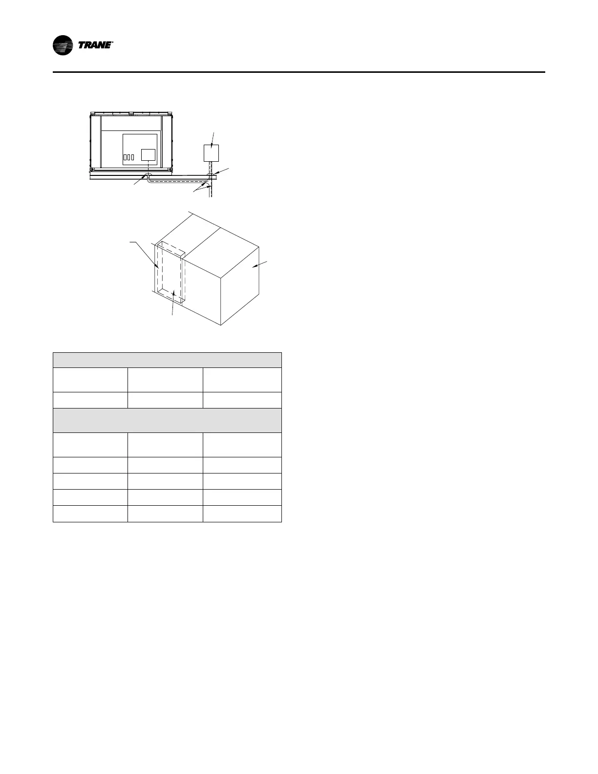
Figure 35. Typical field power wiring (front view)
Field Supplied Survice
Over Current Protection
Pitch Pocket
Pitch Pocket
3-Wire Power
Supply+Ground
Front View Control Box
Electric Heat Control Panel
Gas Heat Control Panel
Steam or Hot Water Control Panel
Heat Control Box
Condenser
Section
1QB1
or 1XD1
Table 20. Customer connection wire range
Units with Main Power Terminal Block
Block Size
Wire Qty Per Phase
Connector Wire
Range
760 Amp
2 4 AWG - 500 kcmil
Units with Main Power Disconnect Switch (Standard and High
SCCR)
Switch Size
Wire Qty Per Phase
Connector Wire
Range
250 Amp
1
3/0 AWG - 350 kcmil
(a)
400 Amp
2 2/0 AWG - 500 kcmil
600 Amp
2 2/0 AWG - 500 kcmil
800 Amp
3 3/0 AWG - 500 kcmil
Note: Non-fused disconnect switch size is calculated by selecting the
size greater than or equal to 1.15 X (sum of unit loads). See unit
literature for unit load values. See following page for circuit
breaker sizing.
(a)
250A Disconnect Switches can accommodate 4 AWG - 4/0 AWG if Lug
Screws are changed to S1A5955 kit (Provided with Unit)
250A Disconnect switch wire binding screws
The 250A disconnect switch (standard and high SCCR)
installed for main power connection accommodates 4
AWG– 350 kcmil wires on the "OFF" side. As shipped from
the factory, the wire binding screws only accommodate 3/0
AWG – 350 kcmil wires. If 4 AWG – 2/0 AWG field power
wiring is used, then the factory installed wire binding
screws must be replaced with those that are provided with
the kit installed near the disconnect switch (these screws
should have a blue top surface). See the kit for instructions
on changing the wire binding screws.
Electrical Service Sizing
To correctly size electrical service wiring for a unit, find the
appropriate calculations listed below. Each type of unit has
its own set of calculations for MCA (Minimum Circuit
Ampacity) and MOP (Maximum Overcurrent Protection).
Read the load definitions that follow and then find the
appropriate set of calculations based on unit type.
Note: Set 1 is for cooling only and cooling with gas heat
units, and set 2 is for cooling with electric heat units.
Load Definitions: (To determine load values, see the
Electrical Service Sizing Data Tables on the following
page.)
LOAD1 = Current of the largest motor (compressor or fan
motor)
LOAD2 = Sum of the currents of all remaining motors
LOAD3 = Current of electric heaters
LOAD4 = Any other load rated at 1 AMP or more
Set 1: Cooling Only Rooftop Units and
Cooling with Gas Heat Rooftop Units
MCA = (1.25 x LOAD1) + LOAD2 + LOAD4
MOP = (2.25 x LOAD1) + LOAD2 + LOAD4
Select a fuse rating equal to the MOP value. If the MOP
value does not equal a standard fuse size as listed in NEC
240-6, select the next lower standard fuse rating.
Note: If selected MOP is less than the MCA, then select the
lowest standard maximum fuse size which is equal
to or larger than the MCA, provided the selected
fuse size does not exceed 800 amps.
Installation