RT-SVX073A-EN
73
Recovery Temperature Sensor value falls below the
Recovery Frost Avoidance Setpoint. The Leaving Recovery
Temperature Sensor is installed in the leaving air stream on
the relief-fan side of the energy wheel. This is
accomplished by opening the Outdoor Air Bypass Damper
removing cold airflow through the wheel while heating
continues with the Relief Air Bypass Damper which
remains in control.
Energy Wheel Frost Avoidance w/
Preheat (Optional)
During active frost avoidance, the preheater function, if
installed, is used to provide additional heat to reduce wheel
frost conditions by energizing the energy recovery preheat
output. Because preheat control is third-party provided, it
can be a significant source of heat and the control will
coordinate the operation of preheat and primary heat. If
primary heat is not active whenever preheat is turned on,
the primary heat capacity control is delayed allowing
preheat to maximize its capacity. Once the Outdoor Air
Bypass Damper has fully opened and additional heat is
required, primary heat sources are allowed.
Energy Wheel Proving Status
Wheel proving uses temperature sensors to validate the
expected operating condition provided by an active wheel.
A wheel that is not active (failed motor, broken belt, etc..)
will not reflect temperature values that normally would be
expected.
When the wheel is off, Wheel Proving Status is set to
“false”. When the wheel is turned on, Wheel Proving Status
is initialized to “true” and Wheel Proving Status update is
pending. There are three temperature sensors monitored to
update Wheel Proving Status: Energy Wheel Leaving Air
Temperature (Tlw), Return Air Temperature (Tra) and
Outdoor Air Temperature (Toa).
When the energy wheel is started, a five-minute ignore time
is applied to Wheel Proving Status update, no proving
calculations are made, and Wheel Proving Status remains
“true”. After this initial ignore time expires, wheel proving
validity and Wheel Proving Status are evaluated
continuously and a five-minute validity timer is started:
If the temperature difference between Toa and Tra is
greater than or equal to 13F wheel proving validity is valid.
When the temperature difference is less than 13F wheel
proving validity is invalid.
If the temperature difference between Tlw and Tra is
greater than or equal to 3F, or the wheel proving validity is
invalid, the validity timer is reset to five minutes and Wheel
Proving Status is set to “true”. If the temperature difference
is less than 3F and wheel proving validity is valid, the
validity timer begins to count down. If the validity timer
times-out (after five continuous minutes), the Energy Wheel
Proving Status is set to “false” and the Energy Wheel
Proving Failure diagnostic is generated.
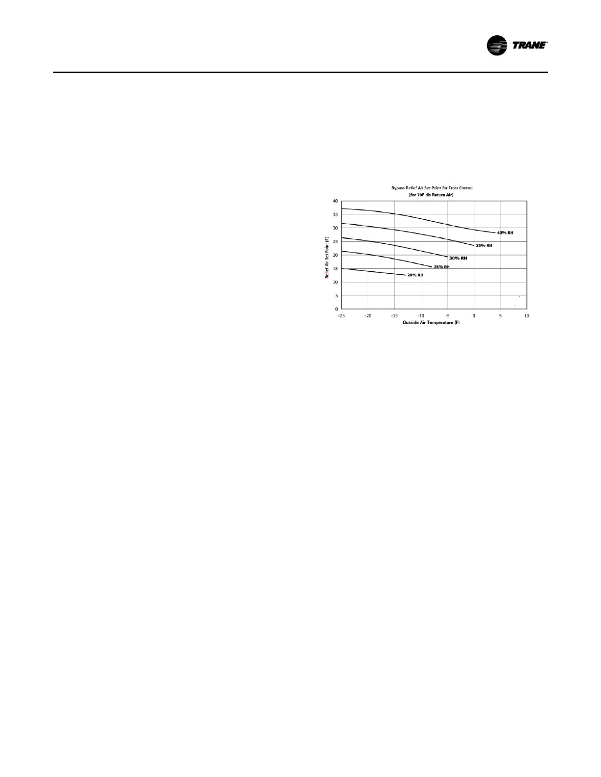
The Leaving Recovery Temp Sensor is installed in the
leaving air stream on the relief-fan side of the energy
wheel.
The figure below provides the relief air temperature
setpoint for 70ºF return air at various precents of relative
humidity.
Figure 39. Energy recovery wheel relief air setpoint
temperatures
Return Fan
The return fan operates to assist the supply fan to
overcome duct system static pressure. The variable speed
return fan operates in coordination with the supply fan
operation, outdoor air damper, and relief damper to
maintain a proper return plenum static pressure. Return
plenum static pressure minimum and maximum setpoints
are adjustable by the user.The controller calculates a
suitable Return Plenum Static Pressure Target within the
minimum and maximum setpoints based on status of the
relief damper, outdoor air damper, and supply fan. The
Return Plenum Static Pressure Target setpoint increases
with increasing outdoor air and relief damper positions.
However, the return fan speed will be limited or reduced if
return plenum pressure approaches the Return Plenum
Static Pressure High Limit.
Return Fan Control with Statitrac (Space
Static Pressure Control)
Return Fan Control with Statitrac (Space Static Pressure
Control) When Space Static Pressure Control (Statitrac) is
configured, return fan operation assists to prevent too low
or high space static pressure conditions. The return fan
control reduces return fan speed under adaptive control in
response to critically low space static pressure.
The return fan control increases fan speed above the
plenum static pressure setpoint target in response to high
space static pressure. This feature, Return Fan Minimum
Capacity Limit Enable, can be disabled from Tracer TU or
the touchscreen display.
Return Fan Startup
Return fan startup is coordinated with supply fan and return
plenum pressure sensor proving. Return fan releases to
Unit Startup