RT-SVX073A-EN
91
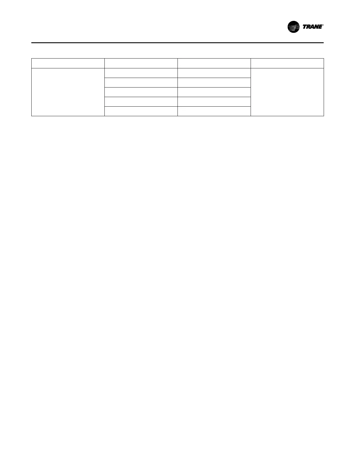
Table 44. Emergency override (continued)
Emergency Override Output Operation Heat Cool Mode Status
Fire Supply fan Off/0% Off
Outdoor air damper Closed
Relief fan / Relief damper
(b)
Off/Closed
Return fan/Relief damper
(b)
Off/Closed
VAV Box Relay De-energized
(a)
Multi Zone-VAV units will perform duct static pressure control.
(b)
Return fan and Relief fan are mutually exclusive.
Operating Mode OFF and Normal Operating
Modes
See operating mode off and other normal operating modes
in Operating Modes section.
Heat/Cool Capacity Lockouts and Limits
The controller provides the following capabilities to lockout
or limit all heat and cool capacity installed in the equipment.
These capabilities interact. Capacity Lockouts have highest
priority. When Heat Lockout Command and Cool Lockout
Command are not locked-out; the control will limit capacity
based on active Cooling Capacity Enable, Primary Heat
Enable or Demand Limit Setpoint. The lowest commanded
value will be honored.
In an example, Heat/Cool Lockouts are not active. Cooling
Capacity Enable is 60%, Primary Heat Enable is 50% and
Demand Limit Setpoint is 40%; DX cooling and electric
heating capacity will be limited to 40%. If the unit had gas
heat, heat capacity would be limited to 50%. Review each
capability below for details.
Capacity Lockouts
Capacity Lockouts are points available to the building
automation network to provide a method to completely
disable DX Cooling, Gas Heating and Electric Heating.
Cool Lockout Command will disable all DX cooling
capacity. Economizer operation is still possible. Heat
Lockout Command will disable all gas and electric heating
capacity. External heating is not controlled directly by the
Symbio800 and will not be locked out with the Heat
Lockout Command.
If both points are True (locked out) at the same time, both
will be honored. Trane Graphical Programming (TGP2) can
be used to control these points.
Cooling Capacity Enable
Cooling Capacity Enable is a building automation interface
point used to limit DX cooling capacity of the equipment, it
does not limit economizer cooling. The 0-100% value limits
the amount of cooling capacity.
Heat Primary Enable
Primary Heat Enable is a building automation interface
point used to limit all forms of primary heat installed in the
equipment. The 0-100% value limits the amount of heating
capacity.
Demand Limit
Demand Limit is a function with building automation
interface points used to limit power consumption of both
heating and cooling capacities installed in the equipment.
Demand Limit does not apply to economizer cooling, gas
heat, external heat nor hot gas reheat.
Demand Limit Request BAS enables and disables the
demand limit function. When set to Limit, the Demand Limit
Setpoint value (0-100%) is applied to the control capacity
calculation. The power consumption result will depend on
number of heating and cooling stages installed and how
each stage maps to the capacity calculation (0-100%).
Filter Status
Filter status is provided by differential pressure monitoring
across individual filters in the equipment airflow and trigger
a binary output when the filter setpoint is achieved. The
following setpoints are available if corresponding filter is
installed:
• Final Filter Diff Press Setpoint, 0.5 – 6.0 IWC (4.0 IWC
default)
• Pre Evap Filter Diff Press Setpoint, 0.5 – 6.0 IWC (4.0
IWC default)
• Energy Wheel Filter Diff Press Setpoint, 0.5 – 6.0 IWC
(4.0 IWC default)
This is in the form of an analog signal to the Symbio
controller which represents pressure drop. Monitoring is
available for individual filters installed in the unit. The
customer can monitor filter differential pressure for the
purpose of filter maintenance. If an alarm is not desirable,
the setpoint can be set to 6.0 IWC which is above the
pressure transducers range. No manual calibration is
necessary as the transducers are factory calibrated.
Startup the Unit
Use the following in conjunction with the “Trane Startup
Checklist,” p. 166, to ensure that the unit is properly
installed and ready for operation. Be sure to complete all of
the procedures described in this section before starting the
unit for the first time.
Unit Startup
 Loading...


