RT-SVX073A-EN
49
33, p. 50 illustrates the recommended piping
configuration for the steam coils.
a. Install a strainer in each return line before the
steam trap.
b. Trap each steam coil separately as described in
Step 10Installation_Steam Heat Units and Step
11Installation_Steam Heat Units to prevent
condensate backup in one or both coils.
c. In order to prevent condensate backup in the piping
header supplying both coil sections, a drain must
be installed utilizing a strainer and a steam trap as
illustrated in Figure 33, p. 50.
Table 18. Hot water and steam coil connection sizes
Hot Water Coil Steam Coil
Unit
Size
Sup-
ply
Re-
turn
Drain/
Vent
Sup-
ply
Re-
turn Vent
90-150
Ton
2 ½ 2 ½ ½ 3.0 1 ¼ 1 ¼
Notes:
1. Type W coils, with center offset headers, are used in Hot Water units;
Type NS coils are used in Steam units.
2. Hot water and Steam units have multiple headers.
3. All sizes are in inches.
4. All connection threads are internal.
Table 19. Hot water and steam heat connection
dimensions
Tons A B Y Diameter
90-105 276 9/16 290 5/16 18 5
120-150 341 5/16 355 1/16 18 5
Figure 31. Hot water and steam heat connection location
A
B
Y
Supply Air Opening
Return Air Opening
Unit bottom view
Inlet
Controls
Outlet
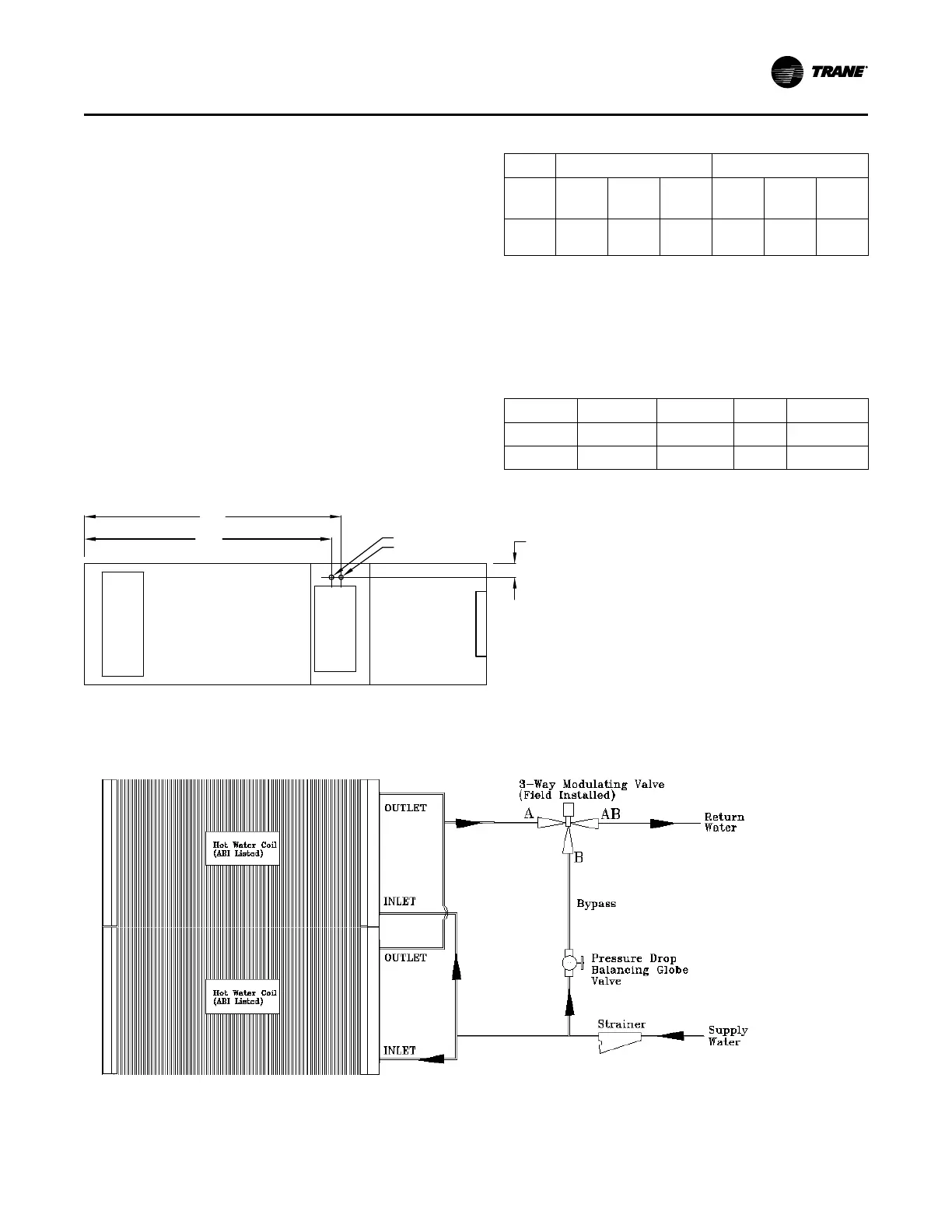
Recommended
Figure 32. Hot water coil piping
Installation