RT-SVX073A-EN
41
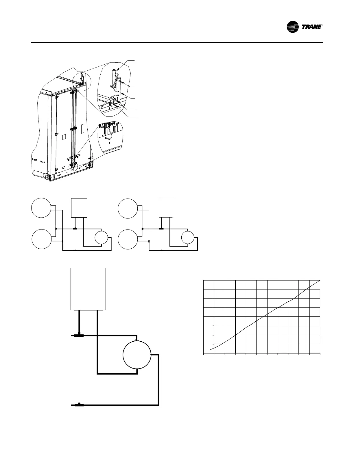
Figure 22. Outside air sensing kit
Sensor
Sensor mounting
slotted bracket
0.188in OD tubing
L bracket
Sensor mounting
screws
Figure 23. Outside air tubing schematic
Upper
Flow
Ring
Low
Lo
NC
C
N
O
Fresh Air
Transducer
Left side
High
Hi
Upper
Flow
Ring
Low
High
Upper
Flow
Ring
Low
High
Upper
Flow
Ring
Low
High
Lo
Fresh Air
Transducer
Left side
Hi
NC
C
NO
Figure 24. Return air pressure tubing schematic
Lo
Outside Air
Return Plenum
Pressure
Fresh Air
Transducer
Left side
Hi
NC
C
NO
Figure 25. Transducer voltage output vs. pressure
input with VCM and Traq™ sensing
0.0
0.5
1.0
1.5
2.0
2.5
3.0
3.5
4.0
Transducer Voltage Output vs. Pressure Input
Pressure (inches w.c.)
Volts
-0.5 0.0 0.5 1.0 1.5 2.0 2.5 3.0 3.5 4.0 4.5 5.0
Units with Statitrac
1. Open the filter access door and locate the Space
Pressure and Duct Supply Pressure control devices,
see the following image for specific location. There are
three tube connectors mounted on the left of the
solenoid and transducers.
2. Connect one end of the field provided 1/4" (length 50-
Installation