Installation - Mechanical
CLCH-SVX013B-EN 35
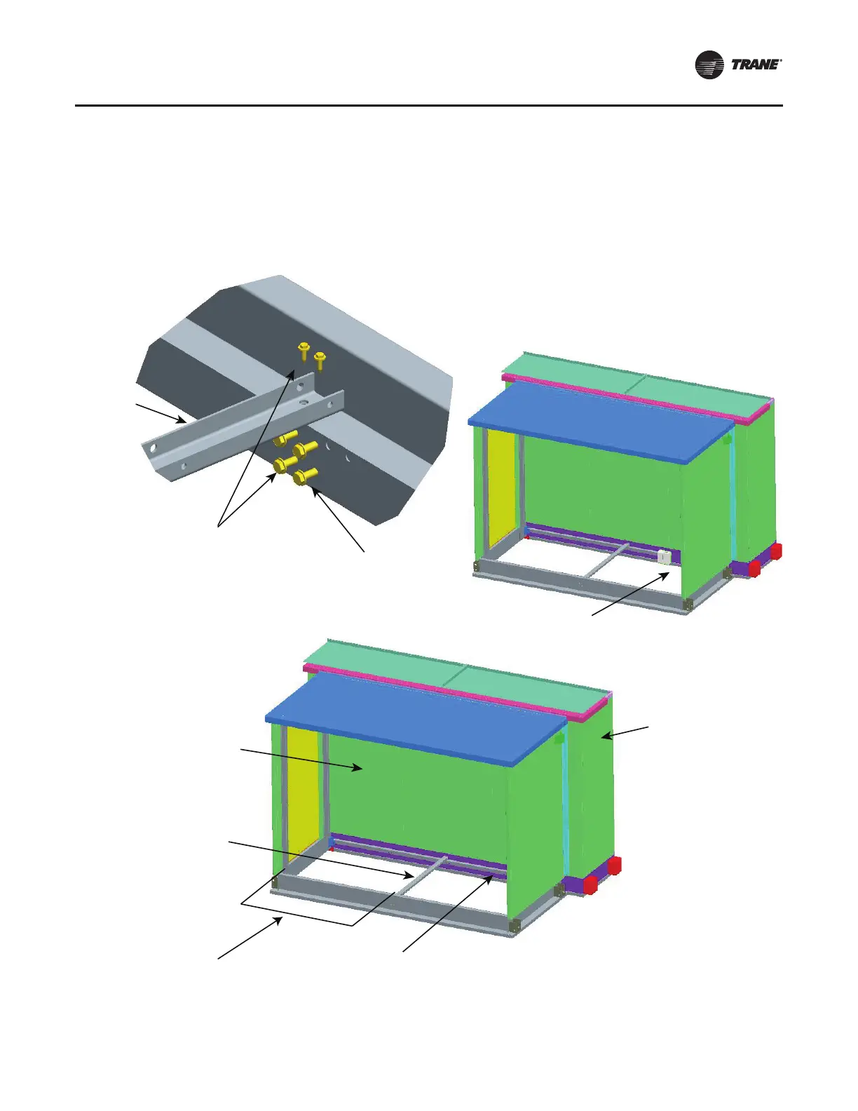
4. Attach the unit base L angle from the pipe cabinet to the
unit base rail. See Step 4 in Figure 46
5. Attach a U channel to the unit base
L angle. Make sure
to cl
ear any coil piping. Make sure to attach enough
nested U channels to comply to the unsupported span.
See Step 5 in Figure 46.
6. Locate the pipe cabinet in place, and reinstall the U
channe
l to the pipe base L angle and reinstall the top U
channel to the nest (see Step 1, Figure 45).
7. When the L angle interferes with the unit base rail
lif
ting lugs
or splice plate, mark and cut L angle section
to clear the component. If excess L angle is not needed
for nested U channel, leave it off. See Figure 46.
Figure 46. Pipe cabinet installation for hurricane appli
cations
Pipe cabinet wall
removed for clarity
Step 6
L angle attached
to unit baserail
Nested U channel
attached to L angle
Unsupported span
Size 3-50 - 52 in. max
Size 57-120 - 34 in. max
Air handler
Step 7
Step 5
Step 4
5/16-18 x .875 screw