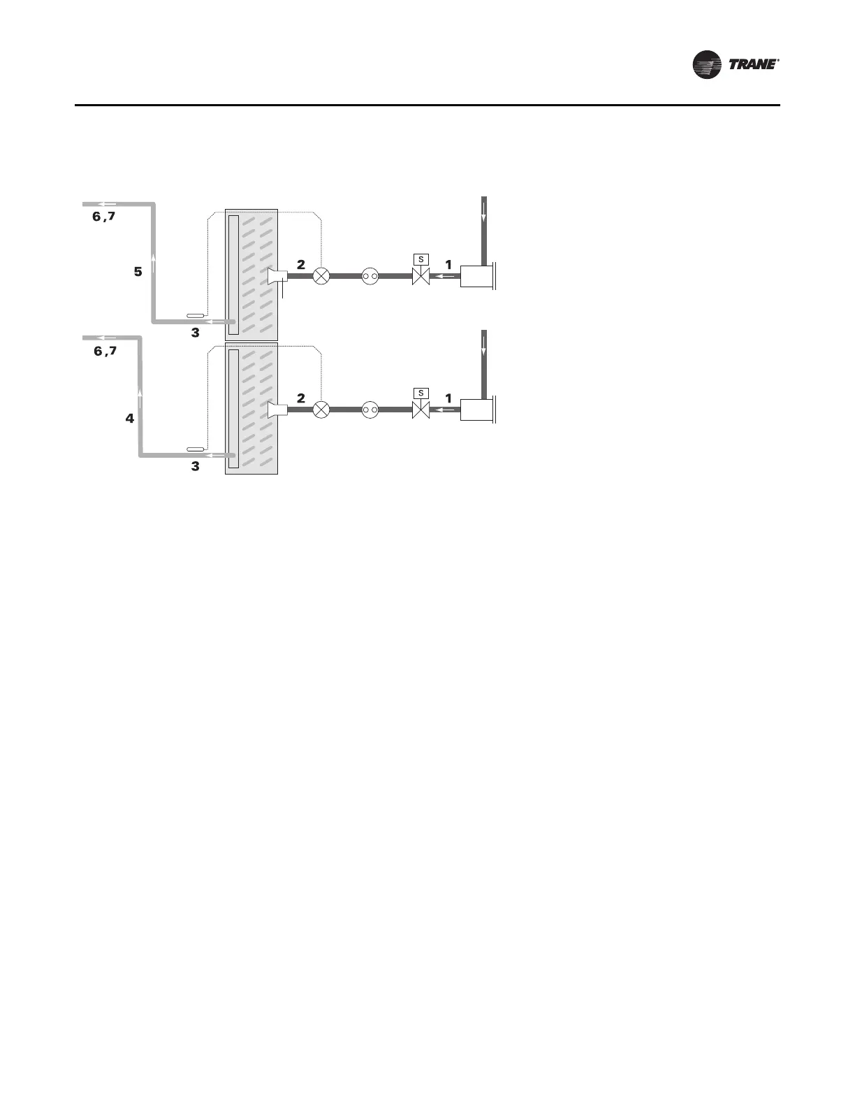
Figure 70. Typical dual-circuit condensing unit: evaporator coil with two distributors
Liquid line
(circuit 2)
Solenoid
valve
Sight
glass
Suction line
(circuit 2)
Thermal
expansion
valve (TXV)
Liquid line
(circuit 1)
Filter drier
Distributor
Suction line
(circuit 1)
Evaporator Coil
with Horizontal-Split (Standard) Circuiting
Piping and Connections
CLCH-SVX013B-EN 53
1. Pitch the liquid lines slightly—1 inch/10 feet —so that
the refrigerant drains toward the evaporator.
2. Provide one expansion valve per distributor.
3. Slightly pitch the outlet line from the suction header
toward the suction
riser—1 inch/10 feet in the direction
of flow. Use the tube diameter that matches the
suction-header connection.
4. The top of the Circuit 1 suction riser must be higher
than the
bottom evaporator coil. Use the tube diameter
recommended for a vertical rise as specified in the
condensing unit application manual.
5. The top of the Circuit 2 suction riser must be higher
than the top evapor
ator coil.
Use the tube diameter
recommended for a vertical rise as specified in the
condensing unit application manual.
6. Pitch the suction lines slightly—1 inch/10 feet —so that
the re
frigerant drains toward the ev
aporator.
7. Insulate the suction lines.