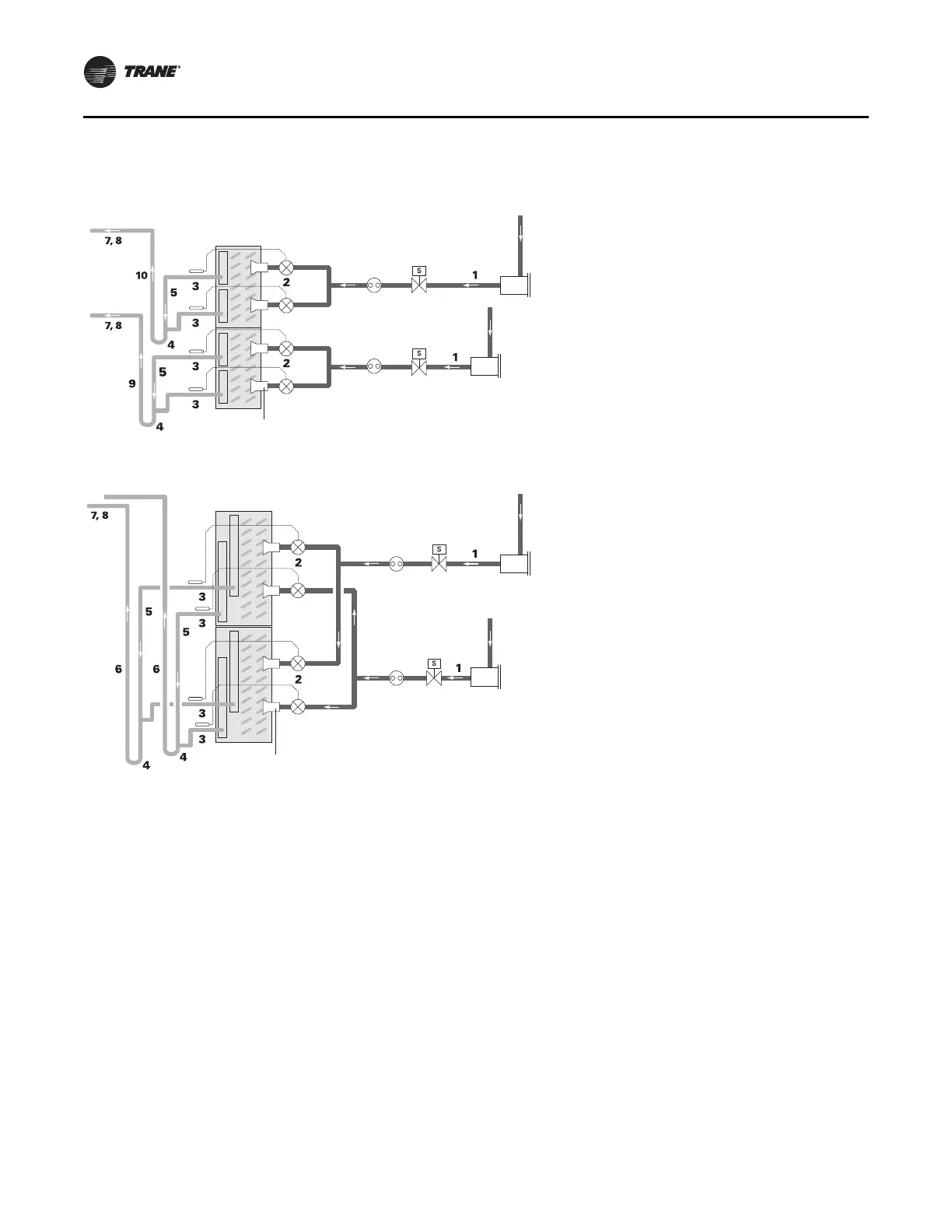
Figure 71. Typical dual-circuit condensing unit: evaporator coil with four distributors
Liquid line
(circuit 1)
Filter drier
Thermal expansion
valves (TXV)
Liquid line
(circuit 2)
Distributor
Solenoid
valve
Sight
glass
Evaporator Coil
with Horizontal-Split (Standard) Circuiting
Thermal expansion
valves (TXV)
Distributor
Suction lines
Evaporator Coil with Intertwined Circuiting
Suction line
(circuit 2)
Suction line
(circuit 1)
Liquid line
(circuit 1)
Filter drier
Liquid line
(circuit 2)
Solenoid
valve
Sight
glass
(circuit 1)
(circuit 2)
1. Pitch the liquid line slightly—1 inch/10 feet —so
that the refrigerant drains toward the
evaporator.
2. Provide one expansion valve per distributor.
3. Slightly pitch the outlet li
ne from
the suction
header toward the suction riser— 1 inch/10 feet
in the directio
n of flow. Use the tube diameter
that matches the suction-header connection.
4. This looks like a trap, but is actually due to the
r
equirement that the refrig
erant gas leaving the
coil flows downward, past the lowest suction-
header outlet, before turning upward. Use the
double-elbow configuration to isolate the TXV
bulb from other suction headers.
5. Use the “horizontal” tube diameter as specified
in the
condensi
ng unit application manual.
6. Use the tube diameter recommended for a
v
ertical r
ise as specified in the condensing unit
application manual. Ensure that the top of the
riser is higher than the evaporator coil.
7. Pitch the suction line slightly—1 inch/10 feet —
so that the re
frigerant drains toward th
e
evaporator.
8. Insulate the suction line.
9. The top of the Circuit 1 suction riser must
be
higher than the bottom evaporator coil. Use
the
tube diameter recommended for a vertical rise
as specified in the condensing unit application
manual.
10. The top of the Circuit 2 suction riser must
be
higher than the top evaporator coil. Use the tube
diameter recommended for a vertical rise as
specified in the condensing unit application
manual.
Piping and Connections
54 CLCH-SVX013B-EN