10
RT-SVX092A-EN
for 72 hours, the trip counter will reset allowing more
auto-resets to occur.
Low Pressure Control (LPC)
When the LPC is opened for 1 continuous second, the
compressors for that circuit is turned OFF. The
compressors will not be allowed to restart for a minimum of
3 minutes.
If four consecutive open conditions occur during an active
call for cooling, the compressors will be locked out, a
diagnostic generated, if applicable, and a manual reset
required to restart the compressors.
High Pressure Control (HPC)
The high pressure controls are wired in series between the
compressor outputs on the Symbio™ controller and the
compressor contactor coils. If the high pressure control
switch opens, the controller senses a lack of current while
calling for cooling and locks the compressors out.
If four consecutive open conditions occur during an active
call for cooling, the compressors will be locked out, a
diagnostic generated, if applicable, and a manual reset
required to restart the compressors.
Air Filters
Filters are to be used with this unit. Units ship from the
factory with filters installed.
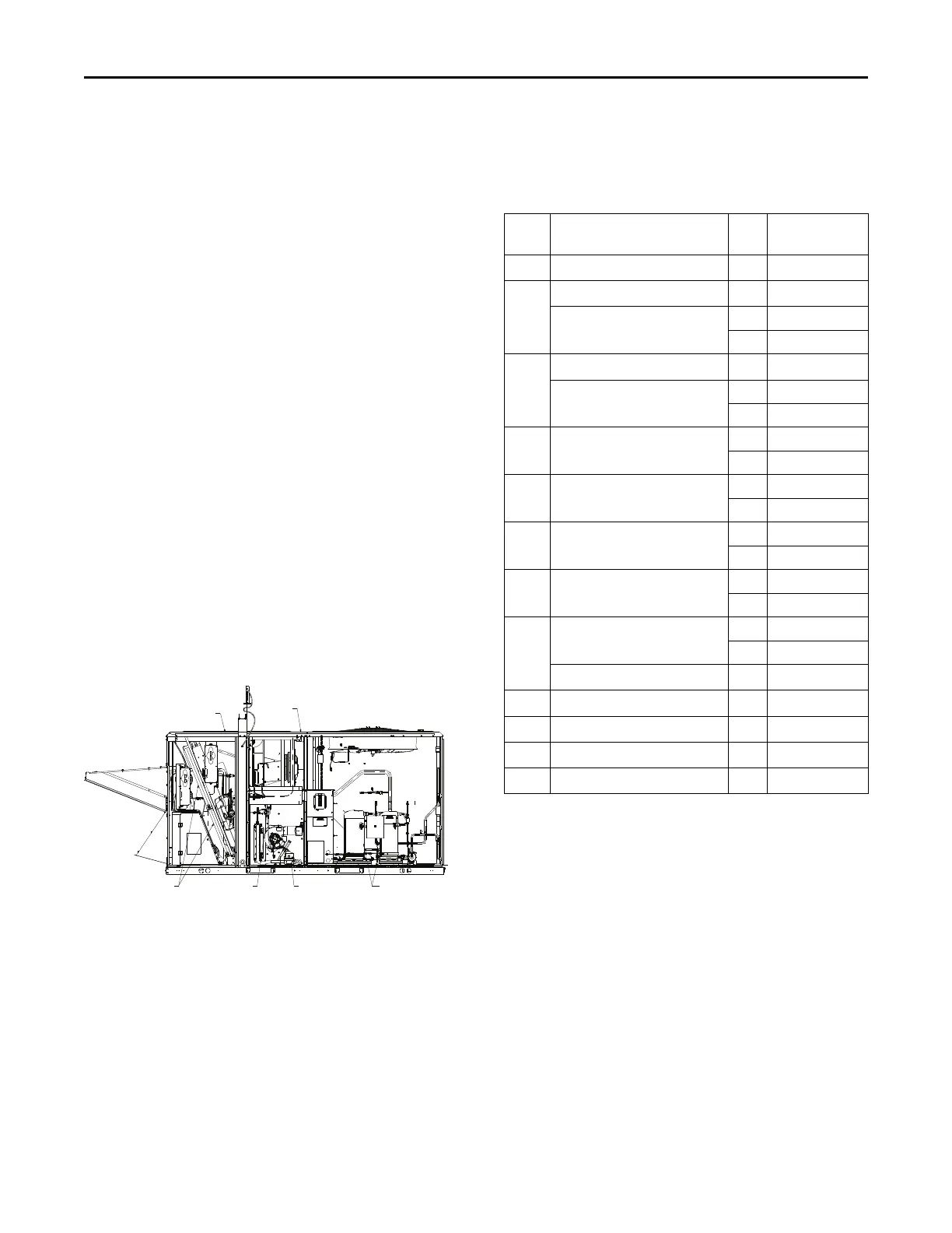
Figure 2. Gas unit overview
SUPPLY AIR
RETURN AIR
PRESSURE SWITCH
GAS VALVE COMPRESSORAIR FILTERS
It is very important to keep the central duct system air filters
clean. Inspect them at least once each month when the
system is in constant operation. (In new buildings, check
the filters every week for the first four weeks.) See the
following table for the required filter size(s).
If the unit has disposable type filters, replace them with
new filters of the same type and size. Do not attempt to
clean disposable filters.
Permanent type filters can be cleaned by washing them
with a mild detergent and water. Confirm the filters are
thoroughly dry before reinstalling them in the unit (or duct
system).
It may be necessary to replace permanent filters annually if
washing fails to clean the filter. Use the same type and size
as originally installed.
Table 1. Recommended standard filters
Tons Unit Model Number Qty Filter Size
(L x W xD)
3 (T,Y)(S,H)K036***(0,A)(L,M,H) 4 20 x 20 x 2
4 (T,Y)SK048***(0,A)L(L,M,H) 4 20 x 20 x 2
(T,Y)HK048***(0,A)L(L,M,H) 2 18 x 24 x 2
3 24 x 16 x 2
5 (T,Y)SK060***(0,A)L(L,M,H) 4 20 x 20 x 2
(T,Y)HK060***(0,A)L(L,M,H) 2 18 x 24 x 2
3 24 x 16 x 2
6 (T,Y)(S,H)K072***(0,A,B)L(L,M,H) 2 18 x 24 x 2
3 24 x 16 x 2
7.5 (T,Y)(S,H)K090***(0,A,B)L(L,M,H) 2 18 x 24 x 2
3 24 x 16 x 2
8.5 (T,Y)(S,H)K102***(0,A,B)L(L,M,H) 2 18 x 24 x 2
3 24 x 16 x 2
10 (T,Y)(S,H)K120***(0,A,B)L(L,M,H) 2 18 x 24 x 2
3 24 x 16 x 2
12.5 (T,Y)SK150***(0,A,B)L(L,M,H) 3 18 x 18 x 2
3 24 x 18 x 2
(T,Y)HK150***(0,A,B)L(L,M,H) 8 20 x 24 x 2
15 (T,Y)HK180***(0,A,B)L(L,M,H) 8 20 x 24 x 2
17.5 (T,Y)HK210***(0,A,B)L(L,M,H) 8 20 x 24 x 2
20 (T,Y)HK240***(0,A,B)L(L,M,H) 8 20 x 24 x 2
25 (T,Y)HK300***(0,A,B)L(L,M,H) 8 20 x 24 x 2
Note: See Table 1, p. 10 to determine unit cabinet size and
refer to cabinet table in dimensions section.
Zone Sensors
Manual Changeover (BAYSENS106*)
This sensor features three system switch settings (Heat,
Cool, and Off) and two fan settings (On and Auto). It is a
manual changeover control with single setpoint.
Manual/Automatic Changeover
(BAYSENS108*)
This sensor features four system switch settings (Heat,
Cool, Auto, and Off) and two fan settings (On and Auto). It
is a manual or auto changeover control with dual setpoint
capability. It can be used with a remote zone temperature
sensor BAYSENS077*.
General Information