50
RT-SVX092A-EN
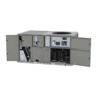
Figure 64. DAS tubing after conversion to horizontal
Vertical slide bracket -
new position
Pickup tube - new
poisition
90 degree elbow
installation location
Figure 65. DAS tubing after conversion to horizontal -
detail
Vertical hole(s) available
for horizontal
Vertical slide bracket -
new position
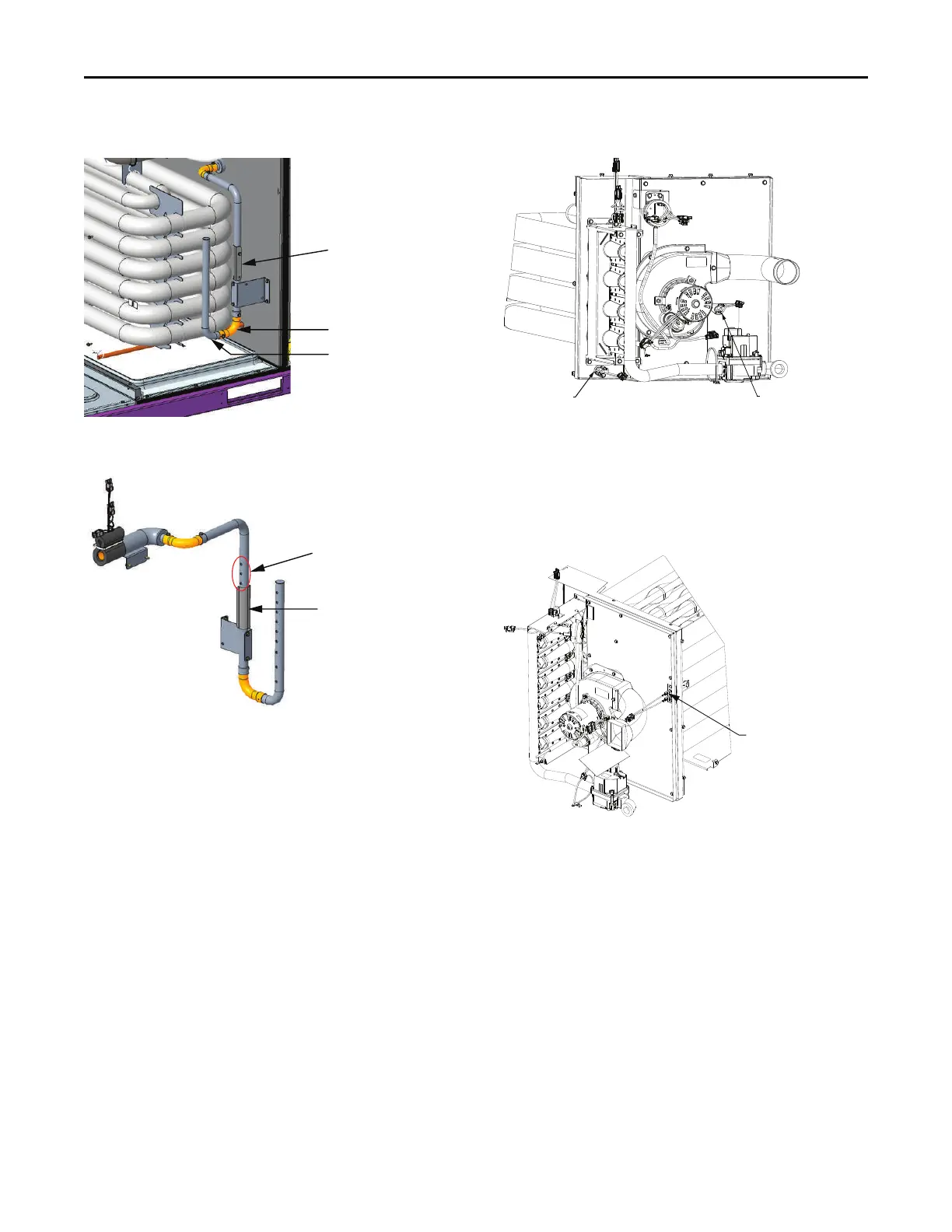
TCO1 Instructions
Note: For complete Gas Heat User information, Operation,
Start-up, Shutdown, and Maintenance refer to “Gas
Heat Operation and Maintenance,” p. 86.
If the unit to be installed in horizontal configuration has a
TCO1 tripping value different from the downflow
configuration, replace TCO1 with the extra TCO1 limit
switch shipped in the unit heater compartment as follows. If
replacement is not required, no further action is required for
TCO1.
1. Remove the heat section access panel.
2. Remove TCO1 from shipping location, which is
attached to the combustion blower motor.
3. Replace and discard the existing TCO1 originally
installed at the factory for down flow operation with the
TCO1 shipped which is shipped with the unit for
horizontal operation.
4. Replace heat section access panel.
Figure 66. TCO1 instructions – A.0 cabinet
Factory installed
TCO1 limit switch
Additional TCO1 limit switch
to be used for horizontal
discharge field conversion
YSK(036-060)* and YHK036* - two stage gas heater
Note: The TCO1 switch is attached by two screws in the
location shown. The switch has short legs on it so
use caution when sliding out of vestibule face during
removal.
Figure 67. TCO1 instructions – B.0/C.0 cabinet
Location of TCO1 limit
to be installed
YHK(048-060)*, Y(S,H)K(072-120)* and YSK150* - two stage gas heater
Installation