60
RT-SVX092A-EN
NOTICE
Component Failure!
Resistance in excess of two and a half (2.5) ohms per
conductor could result in component failure due to
insufficient AC voltage supply.
Do not exceed two and a half (2.5) ohms per
conductor for the length of the run.
Note: Check all loads and conductors for grounds,
shorts, and mis-wiring.
3. Do not run the AC low voltage wiring in the same
conduit with the high voltage power wiring.
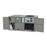
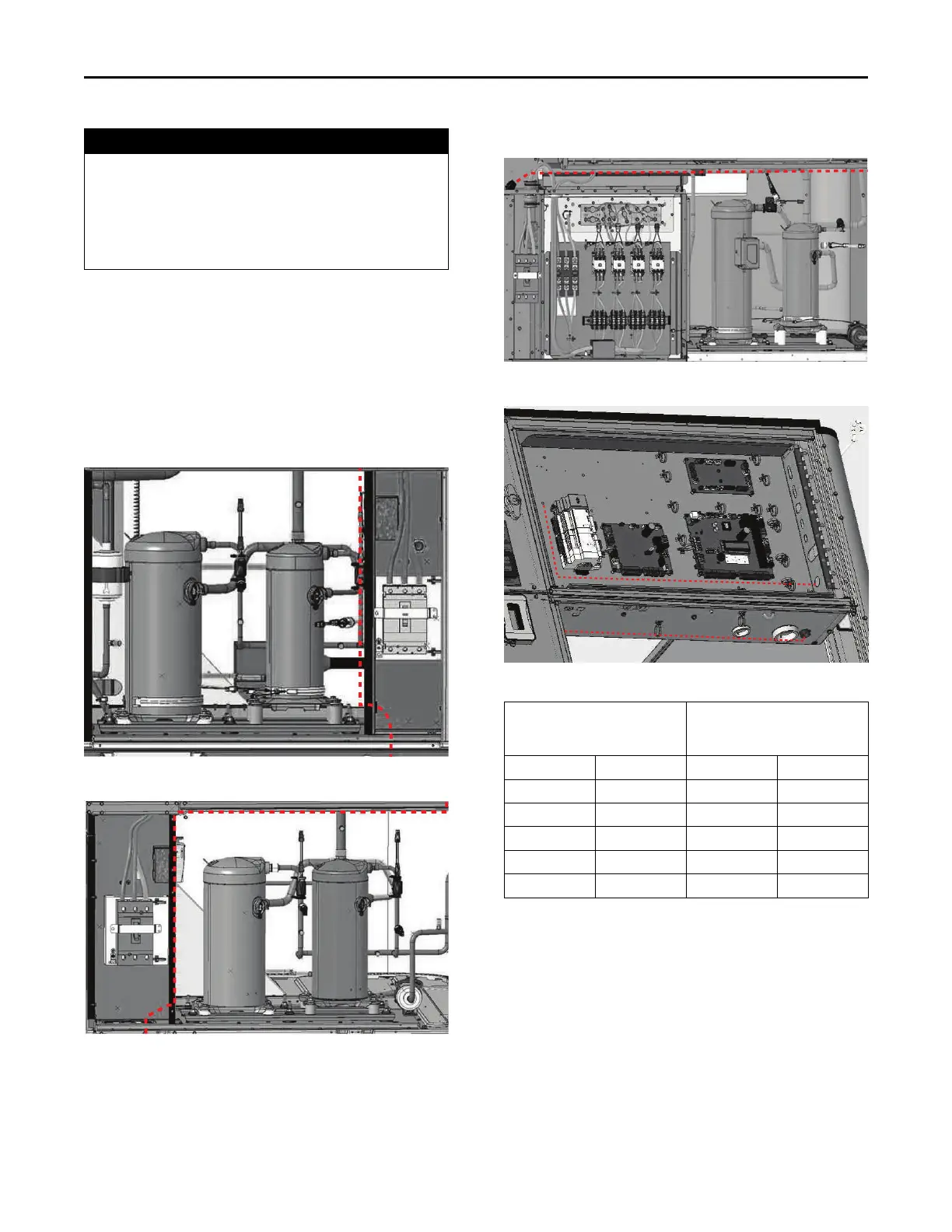
4. Route low voltage wiring per illustrations below.
These illustrations are representative as some models
may appear slightly different. The low voltage wiring
routing is the same.
Figure 84. Low voltage wiring — A/B cabinet
Figure 85. Low voltage wiring — C cabinet
Figure 86. Low voltage wiring — D cabinet
Figure 87. Main control panel low voltage wiring
Table 17. Recommended wire lengths
Wire Size
Maximum recommended wire
length from unit controller to
sensor
AWG mm
2
Meters Feet
22 0.33 0–46 0–150
20 0.50 47–73 151–240
18 0.75 74–117 241–385
16 1.30 118–185 386–610
14 2.00 186–296 611–970
Note: The total resistance of these low voltage wires must not exceed 2.5
Ω/conductor. Any resistance greater than 2.5 Ω may cause the
control to malfunction due to an excessive voltage drop.
Controls using DC Analog Input/Outputs
(Standard Low Voltage Multi conductor
Wire)
Before installing any connecting wiring between the unit
and components utilizing a DC analog input\output signal,
refer to the Dimensions and Weights chapter for the
electrical access locations provided on the unit.
Installation