RT-SVX092A-EN
45
Rigging
WARNING
Heavy Object!
Failure to follow instructions below could result in
unit dropping which could result in death or serious
injury, and equipment or property-only damage.
Ensure that all the lifting equipment used is properly
rated for the weight of the unit being lifted. Each of the
cables (chains or slings), hooks, and shackles used to
lift the unit must be capable of supporting the entire
weight of the unit. Lifting cables (chains or slings)
may not be of the same length. Adjust as necessary
for even unit lift.
See Dimensions and Weights section for rigging
illustration, and center-of-gravity dimensional data. Refer to
the typical unit operating weights table before proceeding.
1. Confirm unit does not need additional moves by fork lift.
2. Prepare unit for rigging as follows:
• For A.0, B.0, and C.0 cabinet units: remove all drill
screws fastening wood protection to metal base rail.
Remove all screws securing wooden protection to
wooden top crate.
• For D.0 and D.1 cabinet units: remove the front and
side base rail bumper protection.
Important: For unit protection, the top crate should
remain in place during lifting. If it must be
removed prior to lifting, protect unit from
damage. Top crate must be removed prior
to operation.
WARNING
Improper Unit Lift!
Failure to properly lift unit in a LEVEL position could
result in unit dropping and possibly crushing
operator/technician which could result in death or
serious injury, and equipment or property-only
damage.
Test lift unit approximately 24 inches (61 cm) to verify
proper center of gravity lift point. To avoid dropping of
unit, reposition lifting point if unit is not level.
3. Rig the unit as shown in the weights section. Attach
adequate strength lifting slings to all four lifting brackets
in the unit base rail. Do not use cables, chains, or slings
except as shown.
4. Install a lifting bar, as shown in the Dimensions and
Weights chapter, to protect the unit and facilitate a
uniform lift. The minimum distance between the lifting
hook and the top of the unit should be 7 feet.
5. Test-lift the unit to confirm it is properly rigged and
balanced, make any necessary rigging adjustments.
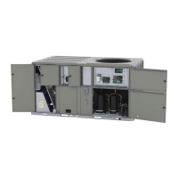
Figure 48. Fork pockets — A.0 and B.0 cabinets
Remove Two Metal Runners
and Three Wooden Boards
Remove Two
Fork Lift
Brackets
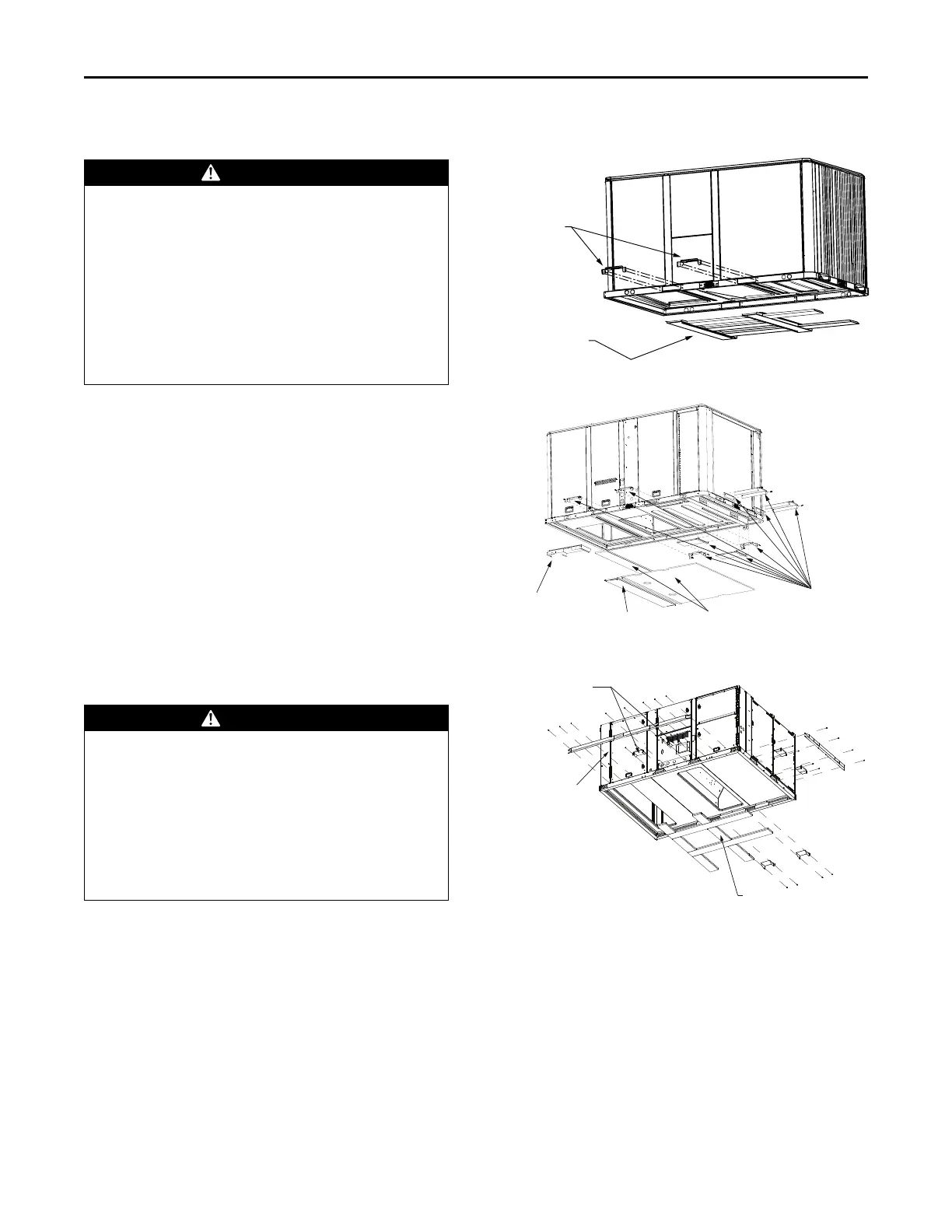
Figure 49. Fork pockets — C.0 Cabinet
NOTICE
Remove this Roof Crub
Alignment Bracket Prior to
Setting Unit onto 60x84-inch
Roof Crub Only
Remove One Metal Runner
Remove Two Wodden Boards
Remove 10 Fork
Lift Brackets
Figure 50. Fork pockets — D.0 and D.1 cabinets
REMOVE WOODEN BOARDS
REMOVE SIX
FORK LIFT BRACKETS
REMOVE TWO
SHIPPING PROTECTIONS
6. Lift the unit enough to allow the removal of base fork
pocket protection components.
• When C.0 cabinet units are installed on a smaller
existing roof curb (50-inch x 84-inch) for
replacement applications, do not remove alignment
bracket. Use the bracket to properly align duct
openings.
Note: See table in dimensions section for cabinet sizes.
7. Downflow units: Align the base rail of the unit with the
curb rail while lowering the unit onto the curb. Confirm
the gasket on the curb is not damaged while positioning
the unit.
Installation