RT-SVX092A-EN
57
5. Remove the plug knockout in the bottom of the
drainpan to convert it to through the base drainage.
6. Plug the original condensate drain opening with a field
supplied 3/4-inch NPT plug.
7. Slide the condensate drain pan back into the unit. Align
the drain support with the grommeted opening in the
rear support panel and push until the support is seated
in the grommet.
8. Replace the front support panel. Align the plugged
condensate drain pan coupling in the grommeted hole
as the panel is put in place.
9. Replace evaporator access panel, left control box door,
and heat section panel.
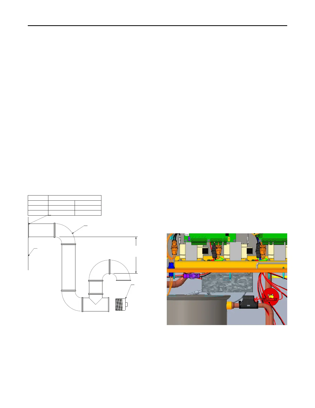
A condensate trap must be installed at the unit due to the
drain connection being on the negative pressure side of
the fan. Install the p-trap using the guidelines in Figure 82,
p. 57.
A condensate drain line must be connected to the p-trap.
Pitch the drain lines at least 1/2-inch for every 10 feet of
horizontal run to assure proper condensate flow. Do not
allow the horizontal run to sag causing a possible double
trap condition. This can result in condensate backup due to
air lock.
Figure 82. Condensate trap installation
1.5" MIN. (381 MM)
4"+ REQUIRED FOR
HIGHER STATICS
Drain Pan Type Connection
CABINET
STD STAINLESS
A.0/B.0/C.0
3/4" NPT 3/4" NPT
D.0/D.1
1" PVC Socket 1" NPT
UNIT POST
CLEANOUT
PLUG
FIELD SUPPLIED PIPING
Drain Pan Removal (Units with
Condensate Overflow Switch Option)
Before drain pan removal, the switch wire must be
disconnected from wire tie on panel and/or any tape before
drain pan can be removed.
Avoid catching the wire on the bottom of indoor coil or any
protrusion.
Note: When reversing the drain pan on some units, the
condensate overflow switch will need to be moved to
the second hole in its bracket to avoid contact with
headers or indoor coil.
Furnace Condensate Drain
Modulating gas units are equipped with a furnace
condensate drain system to evacuate any condensation
(water) that may form inside the heat exchanger during
cooling system operation. The unit does not condense
during heating operation. Neutralization is not necessary
as the condensate drainage is water only and is not acidic.
Filter Installation
The quantity of filters is determined by unit size. Refer to
Table 1, p. 10 for filter sizes. Access to the filters is
obtained by removing the filter access panel.
Note: Do not operate the unit without filters.
Outdoor Motor Controllers
When either an outdoor motor or an outdoor motor
controller fail, the motor and controller must be replaced
together as received in the service kit since they are a
paired tuned drive/motor assembly. Failure to do so could
result in loss of unit function.
In B.0 and C.0 cabinets, the outdoor motor controller is
located below the control box in the condenser section.
See figure below.
Figure 83. Location of outdoor motor controllers –
B.0 and C.0 cabinets
Installation