56
RT-SVX092A-EN
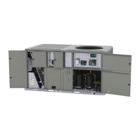
Figure 80. Vertical tube hole(s) location
Hole or holes
located here
Vertical slide bracket
positioned to block
hole(s)
Vertical DAS tube
Table 14. Sizing natural gas pipe mains and branches
Iron Pipe Size (IPS) Inches
Length
of Pipe
(Ft.)
1/2-in.
Pipe
3/4-in.
Pipe
1-in.
Pipe
1¼-in.
Pipe
1½-in.
Pipe
15 76 176 345 750 1220
30 52 120 241 535 850
45 43 99 199 435 700
60 38 86 173 380 610
75 - 77 155 345 545
Note: Capacity of pipe of different diameters and lengths in Cu. Meter per
Hr. with pressure drop of 74.6 Pa and specific gravity of 0.60.
Table 15. Iron pipe size (SI) millimeters
Iron Pipe Size (SI) Millimeters
Length of
Pipe
(Meters)
15 mm
Pipe
20 mm
Pipe
25 mm
Pipe
32 mm
Pipe
40 mm
Pipe
4.6 2.15 4.98 9.76 21.23 34.54
9.1 1.47 3.39 6.82 15.14 24.06
13.7 1.21 2.80 5.63 12.31 19.82
18.3 1.07 2.43 4.89 10.76 17.27
22.9 — 2.18 4.38 9.76 15.40
Note: Capacity of pipe of different diameters and lengths in Cu. Meter per Hr. with
pressure drop of 74.6 Pa and specific gravity of 0.60.
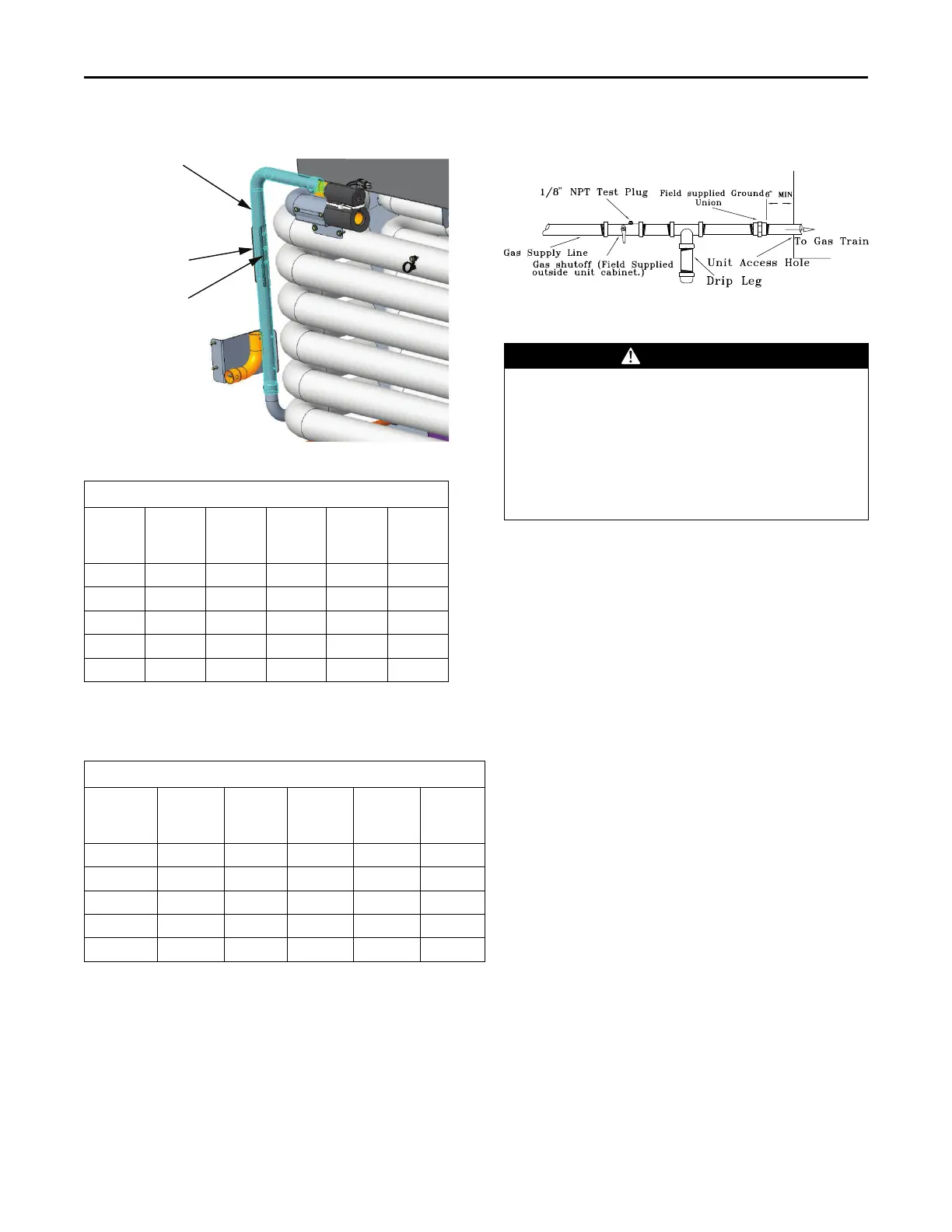
Figure 81. Schematic diagram for field gas piping to
units
Condensate Drain Configuration
WARNING
Hazardous Voltage!
Failure to disconnect power before servicing could
result in death or serious injury.
Disconnect all electric power, including remote
disconnects before servicing. Follow proper lockout/
tagout procedures to ensure the power can not be
inadvertently energized. Verify that no power is
present with a voltmeter.
An evaporator condensate drain connection is provided on
each unit. Refer to “Ductwork,” p. 40 for the appropriate
drain location.
The A.0, B.0, and C.0 cabinet condensate drain pan is
convertible. Refer to “Ductwork,” p. 40 drawings. It can be
converted to drain condensate from the front side of the
unit or through the base.
To convert drain condensate out the front of unit:
1. Remove evaporator access panel, left control box door,
and heat section panel.
2. Remove the support panel that the condensate drain
pan exits through.
3. Slide the condensate drain pan out of the unit and
rotate 180°.
4. Slide the condensate drain pan back into the unit. Align
the drain with the grommeted opening in the rear
support panel and push until the coupling is seated in
the grommet.
5. Replace the front support panel. Align the condensate
drain pan support in the grommeted hole as the panel
is put in place.
6. Replace evaporator access panel, left control box door,
and heat section panel.
To convert drain condensate through the base of unit:
1. Remove evaporator access panel, left control box door,
and heat section panel.
2. Remove the support panel that the condensate drain
pan exits through.
3. Slide the condensate drain pan out of the unit.
4. Place on a level surface in the position it was removed
from the unit.
Installation