RT-SVX092A-EN
31
Clearances
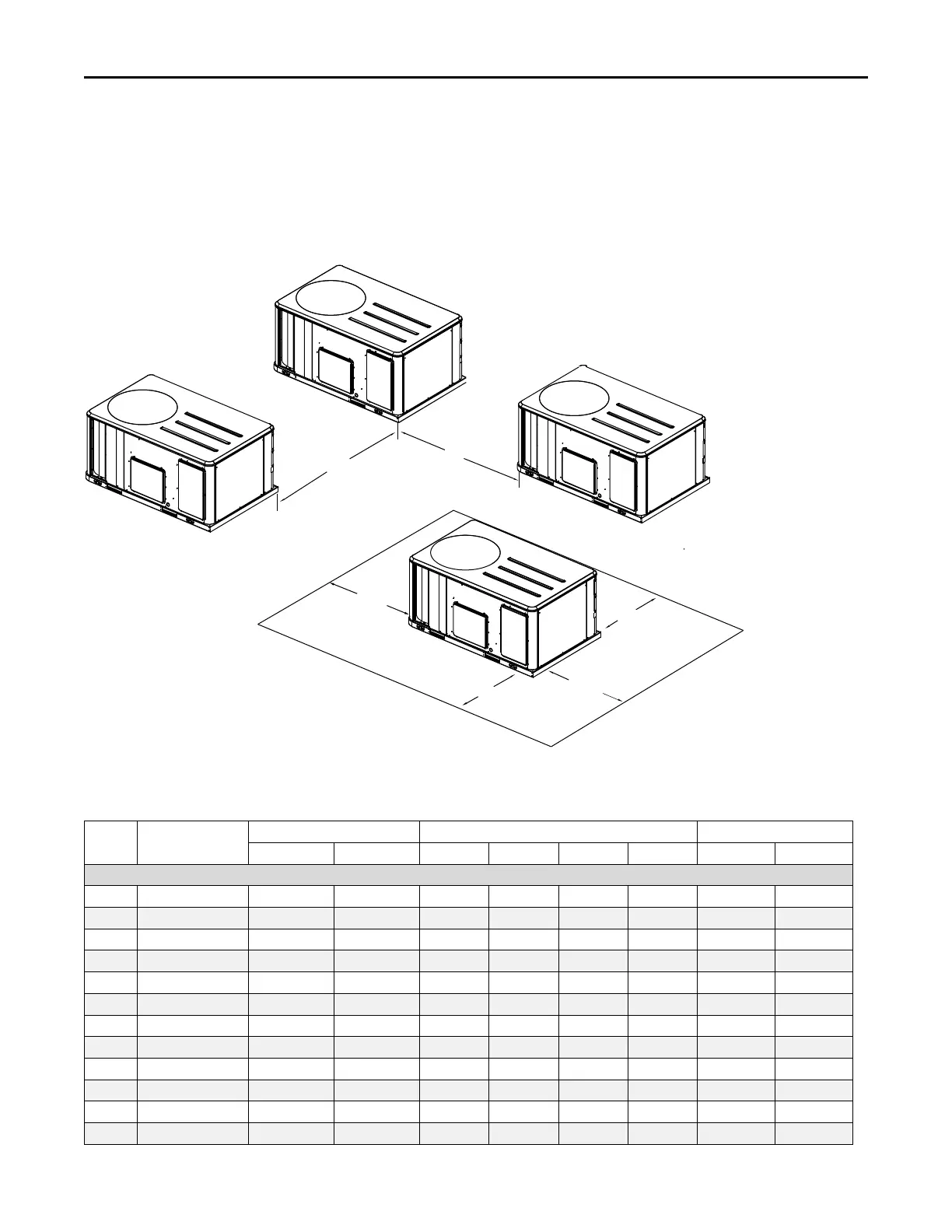
Figure 34, p. 31 illustrates the minimum operating and
service clearances for either a single or multiple unit
installation. These clearances are the minimum distances
necessary to assure adequate serviceability, cataloged unit
capacity, and peak operating efficiency. Providing less than
the recommended clearances may result in condenser coil
starvation, “short-circuiting” of exhaust and economizer
airflows, or recirculation of hot condenser air.
Figure 34. Typical installation clearances for single and multiple unit applications
Side by Side
Note 1
End to End
Note 1, 2
7’0”
2134 MM
6’0”
1829 MM
3’0”
914 MM
Single Unit
3’0”
914 MM
3’0”
914 MM
4’0”
1219 MM
Notes:
1. When equipped with economizer
or barometric relief damper, clearance
distance is to be measured from
protruding hood instead of base.
2. Clearance is the same if any unit
is rotated 180 degrees.
4’0”
1219 MM
for D cabinet
5’0”
1525 MM
for D cabinet
5’8” for D cabinet
1727 MM
Weights
Table 3. Model weights, corner weights (lbs) and center of gravity dimensions (in.)
Tons Unit Model No.
Model Weights
(a)
Corner Weights
(b)
Center of Gravity (in.)
Shipping
Net A B C D
Length
Width
Standard Efficiency
3 TSK036 667 589 184 147 111 147 31 19
4 TSK048 686 609 194 153 111 152 30 19
5 TSK060 705 629 202 154 112 160 30 19
6 TSK072 986 892 319 267 139 167 41 18
7.5 TSK090 1008 914 327 273 143 171 41 18
8.5 TSK102 1029 935 335 280 146 175 41 18
10 TSK120 1044 950 340 284 148 178 41 18
12.5 TSK150 1412 1218 464 343 175 236 43 21
15 TSK180 2040 1820 611 447 322 440 52 36
17.5 TSK210 2070 1850 612 463 334 441 53 36
20 TSK240 2140 1920 689 472 309 451 50 34
25 TSK300 2190 1970 684 484 332 469 51 35
Dimensions and Weights