RT-SVX092A-EN
51
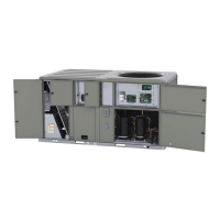
Figure 68. TCO1 instructions – D.0/D.1 cabinet
Factory installed
TCO1 limit switch
Additional TCO1 limit switch
to be used for horizontal
discharge field conversion
YHK150* and Y(S,H)K(180-300)* - two stage gas heater
Return Air Smoke Detector
A.0, B.0, and C.0 Cabinet Units
The factory installed Return Air Smoke Detector is installed
in the downflow discharge position. No additional field
setup is required.
If a unit is to be converted to Horizontal discharge, the
following conversion must be performed:
1. If the unit has an economizer, it must be pulled out in
the operating position.
2. Remove the 3 screws from the mounting brackets.
Refer to downflow view for screw locations.
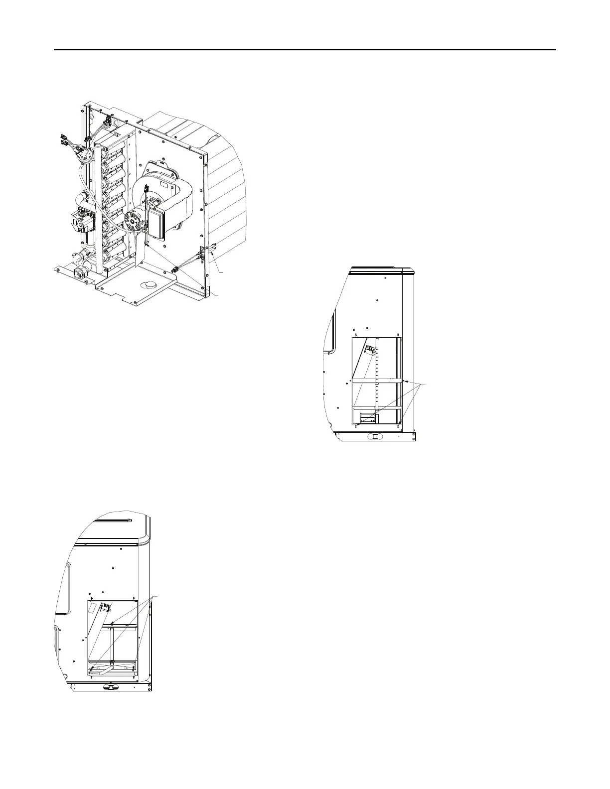
Figure 69. Downflow view
3. Lift the tube and bracket from the downflow duct
opening. Rotate the tube and bracket assembly 180°
ensuring that the holes on the sensing tube face away
from the unit and face the return air ductwork.
Notes:
• Refer to horizontal views below.
• Ensure that the flexible tubing lies flat on
the base pan surface.
4. Slide the top bracket down the sensing tube. Secure
right side of the bracket to the middle duct cover screw
hole shown in Figure 70, p. 51. For B.0 and C.0
cabinets, secure the left side of bracket with self
tapping screw.
5. Using the remaining 2 screws removed in Step 2,
secure the bottom bracket.
Figure 70. Horizontal view
D.0 and D.1 Cabinet Units
The factory installed return air smoke detector is installed in
the downflow discharge position for D.0 and D.1 cabinet
units. No additional field setup is required.
If a unit is to be converted to horizontal discharge, the
following conversion must be performed.
1. If the unit has an economizer, it must be pulled out in
the operating position.
2. Remove the two screws from the mounting brackets.
Installation