52
RT-SVX092A-EN
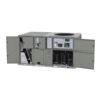
Figure 71. Downflow bracket installation (view from
horizontal return duct)
3. Lift the tube and bracket from the downflow duct
opening. Rotate the tube and bracket assembly 90
degrees and confirm the holes on the aluminium
sensing tube face away from the unit and face the
return air ductwork.
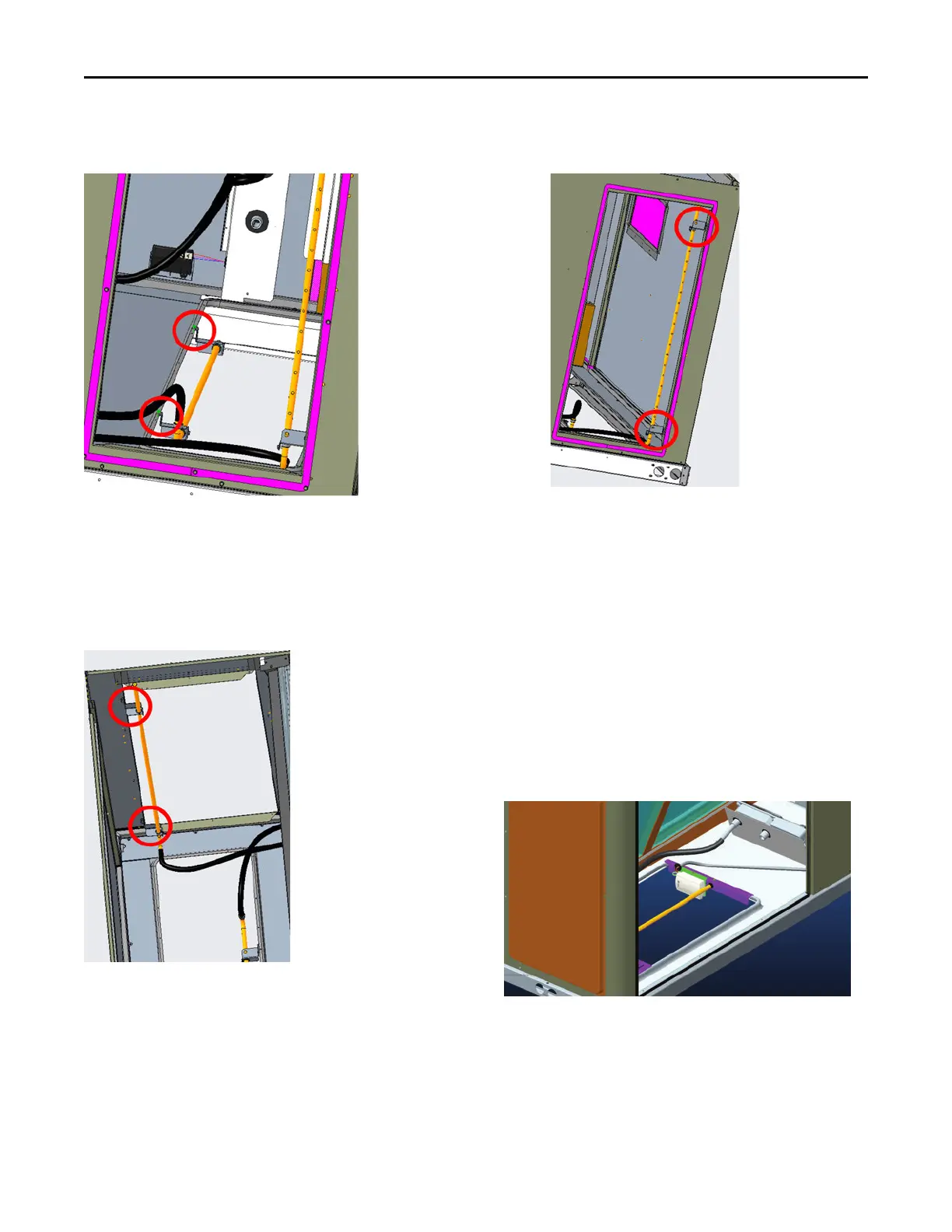
Figure 72. Horizontal bracket installation (top view of
unit)
Note: Flexible tubing should lay flat on the base pan
surface.
4. Slide the top bracket down the aluminium sensing tube.
• For units with standard or low leak economizers,
secure the tube to the top right side of the
horizontal opening flange (right side when viewed
from outside unit facing horizontal supply). See
Figure 73, p. 52.
Figure 73. Horizontal bracket installation (view
from horizontal return duct)
5. Use the remaining two screws and bracket removed in
Step 2, secure the bottom bracket.
Air-Fi® Wireless Communication
Interface
The factory installed wireless communications interface is
installed in the downflow discharge position.
If converting to horizontal discharge, perform the following:
1. If the unit has an economizer, it must be pulled out in
the operating position.
2. Remove the screw from the mounting bracket. Refer to
downflow view for screw and bracket location.
Figure 74. Wireless communication interface -
downflow
3. Mount the bracket in the horizontal discharge location.
Refer to horizontal view for screw and bracket location.
Installation