RT-SVX092A-EN
41
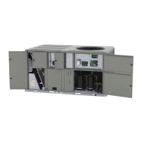
Figure 40. C.0 cabinet – horizontal airflow, supply and return
4 1/4”
108 MM
32 1/4”
832 MM
19 1/4”
489 MM
SUPPLY
RETURN
16 3/4”
425 MM
9 3/8”
238 MM
32 1/4”
832 MM
4 3/4”
120 MM
27 5/8”
701 MM
3/4 - 14 NPT DIA. HOLE
CONDENSATE DRAIN
3 7/8”
98 MM
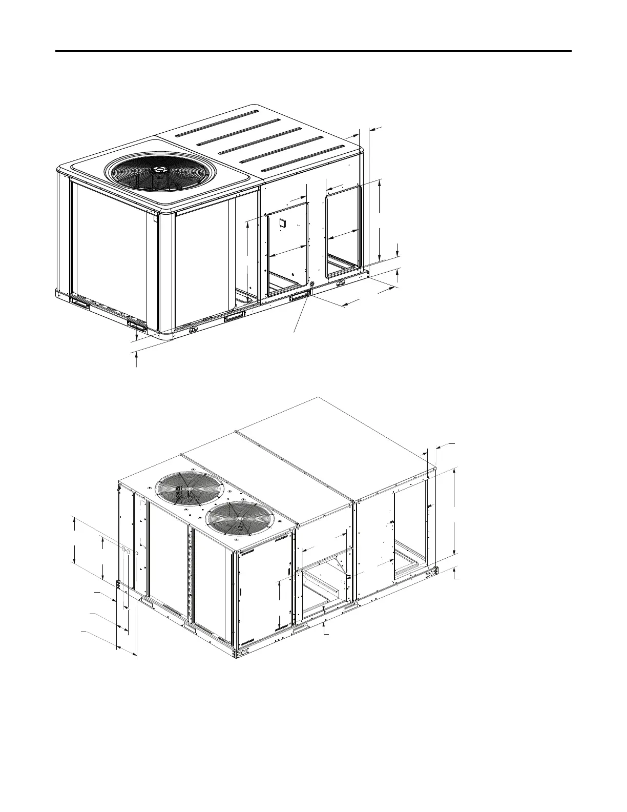
Figure 41. D.0 and D.1 cabinets – horizontal airflow, supply and return
22 3/8''
[570]
23 11/16''
[603]
26 3/4''
[679]
29''
[737]
20 ''
[508]
46 1/2''
[1181]
5 1/4''
[133]
6''
[153]
5 1/2''
[141]
25 1/2''
[648]
4 9/16''
[114]
7 15/16''
[202]
14 1/16''
[357]
SUPPLY
RETURN
Supply and return air openings as viewed from a downflow
configuration are shown in the following drawings.
Elbows with turning vanes or splitters are recommended to
minimize air noise due to turbulence and to reduce static
pressure.
When attaching the ductwork to the unit, provide a water
tight flexible connector at the unit to prevent operating
sounds from transmitting through the ductwork.
To allow access for fan and fresh air option servicing, do
not attach ductwork over panel above the supply opening.
All outdoor ductwork between the unit and the structure
should be weather proofed after installation is completed.
Installation