Installation Mechanical
RTHD-SVX02H-EN 57
Full Heat Recovery Condenser Water Tem-
perature Requirements and Control
D
WARNING
The following application conditions
must be satised, otherwise the unit will
be damaged easily!
1. Operation control of the pump: the operation of the
pump must correspond with the pump start-stop
signal of the UC800 controller of the unit.
2. Setting of water ow switch: the ow switch node
of the unit is not allowed to be short-connected, and
it should be connected with the water system ow
switch, and the ow rate is not less than 60% of the
rated ow when the water ow switch is closed.
3. Establishment time of ow: Time between ow
switch close and water pump runs should not exceed
5 minutes.
4. In addition to the mode switching process, the two
water pumps of the full heat recovery unit are not
allowed to run simultaneously.
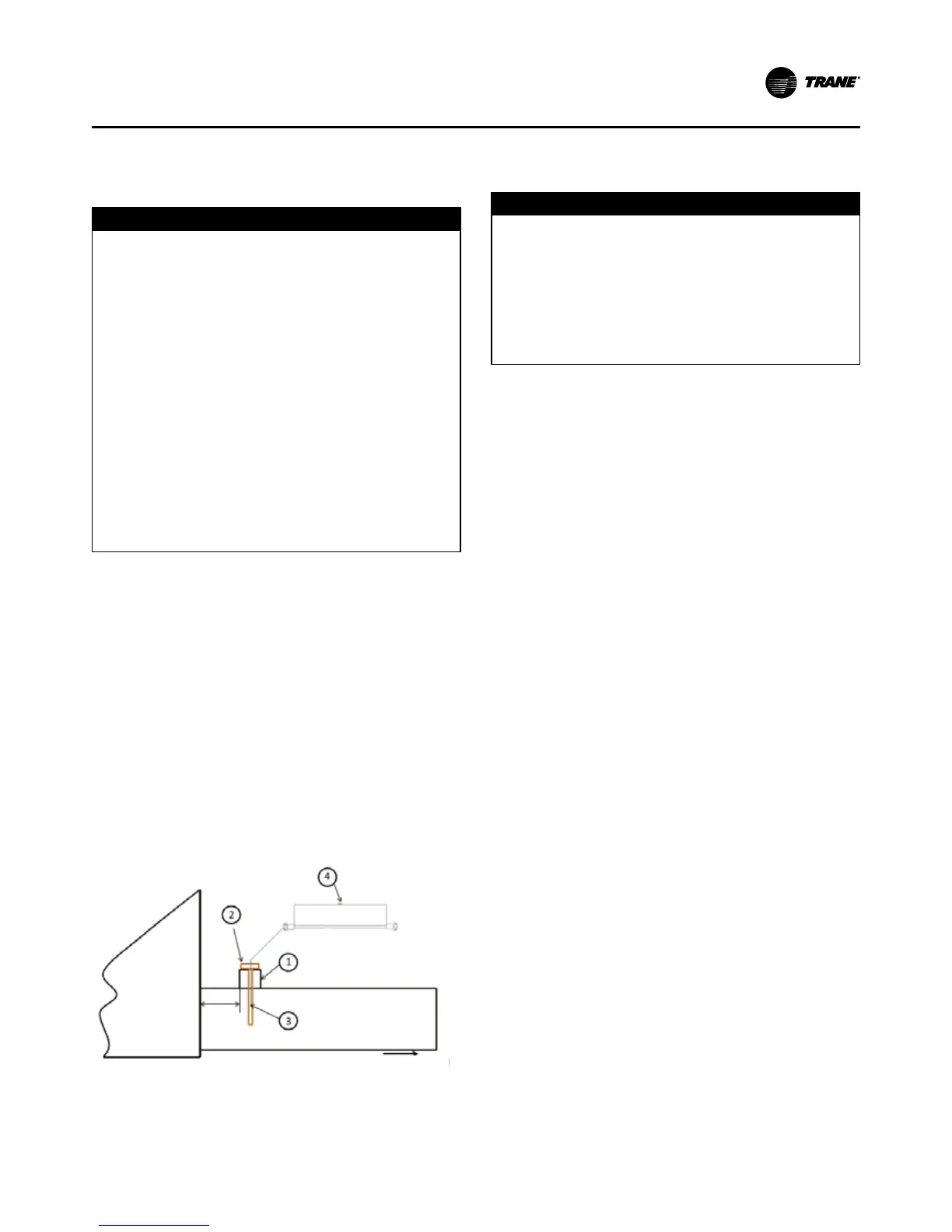
Installation Of Water Tank Temperature
Sensor
The RTHD full heat recovery unit needs to collect the
temperature of the client’s water tank at run time for load
control, and the installation of the temperature sensor of
the tank can be referenced below.
Part 1 is provided by the customer. The internal thread
specification of the joint and temperature sensor tem-
perature package is 1/2-14NPT. Parts 2, 3, 4 are provided
by Trane. In order to avoid affecting the measurement
accuracy, the distance between the insertion position
of the temperature sensor and the water tank must not
exceed 200mm. The temperature sensor is connected to
the temperature acquisition module by 20 meters long
connecting line, and the temperature of the water tank is
transmitted to the unit control cabinet.
Client water box
Max. 200mm
Receive full heat recovery condenser inlet
1. Temperature sensor temperature well connector.
2. Temperature sensor temperature well.
3. Temperature sensor
4. 20 meters long connecting line.
Water Treatment
D
CAUTION
Proper Water Treatment!
The use of untreated or improperly treated water in a
RTHD may result in scaling, erosion, corrosion, algae or
slime. It is recommended that the services of a qualied
water treatment specialist be engaged to determine
what water treatment, if any, is required. The Trane
Company assumes no responsibility for equipment fail-
ures which result from untreated or improperly treated
water, or saline or brackish water.
Using untreated or improperly treated water in these
units may result in inefficient operation and possible
tube damage. Consult a qualified water treatment spe-
cialist to determine whether treatment is needed.
Water Pressure Gauges and Thermome-
ters
Install field-supplied thermometers and pressure gauges
(with manifolds, whenever practical) as shown in Figure
27. Locate pressure gauges or taps in a straight run of
pipe; avoid placement near elbows, etc. Be sure to install
the gauges at the same elevation on each shell if the
shells have opposite-end water connections.
To read manifolded water pressure gauges, open one
valve and close the other (depending upon the reading
desired). This eliminates errors resulting from differently
calibrated gauges installed at unmatched elevations.