General Information
RTHD-SVX02H-EN 17
Installation Overview
For convenience, Table 3 summarizes responsibilities that
are typically associated with the RTHD chiller installation
process.
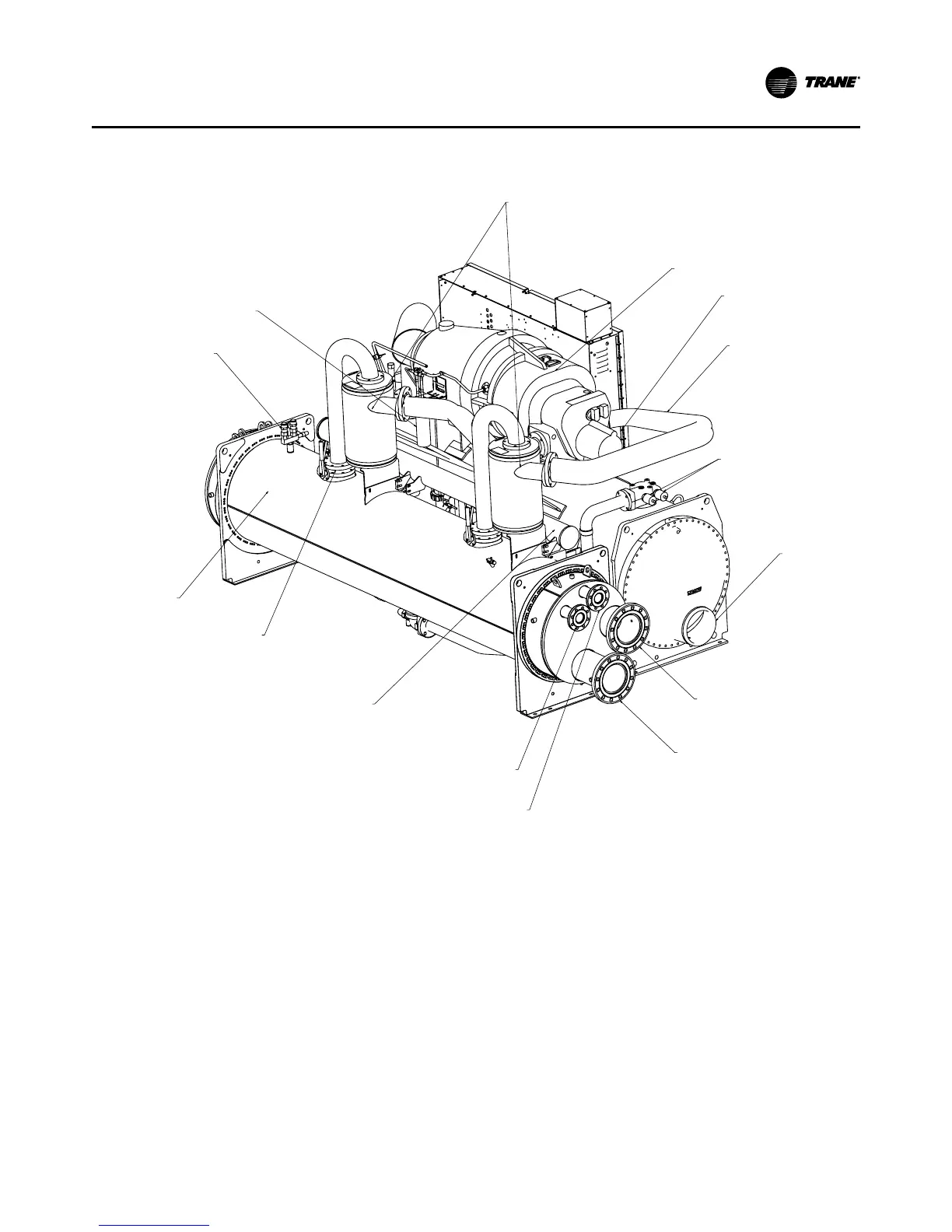
Figure 7. Component Location for Typical RTHD Partial Heat Reclaim Unit (Back View)
Oil Separator
Compressor
Unit Nameplate
(On side of starter/
control pane
Discharge Line
Evaporator
Water Inlet
Standard Condenser
Water Inlet
Partial Heat Reclaim
Condenser Water Inlet
Partial Heat Reclaim
Condenser Water Outlet
Oil Sump (The oil distribution
system is located between the
condenser and the evaporator.)
Service Valves (With
Refrigerant Isolation Valve
Option Only)
Standard Condenser
Water Outlet
EXVs
Relief Valves
Oil Filter (Cold)
Hot Oil Filter is hidden
from view.
Standard/Partial
Heat Reclaim
Condenser