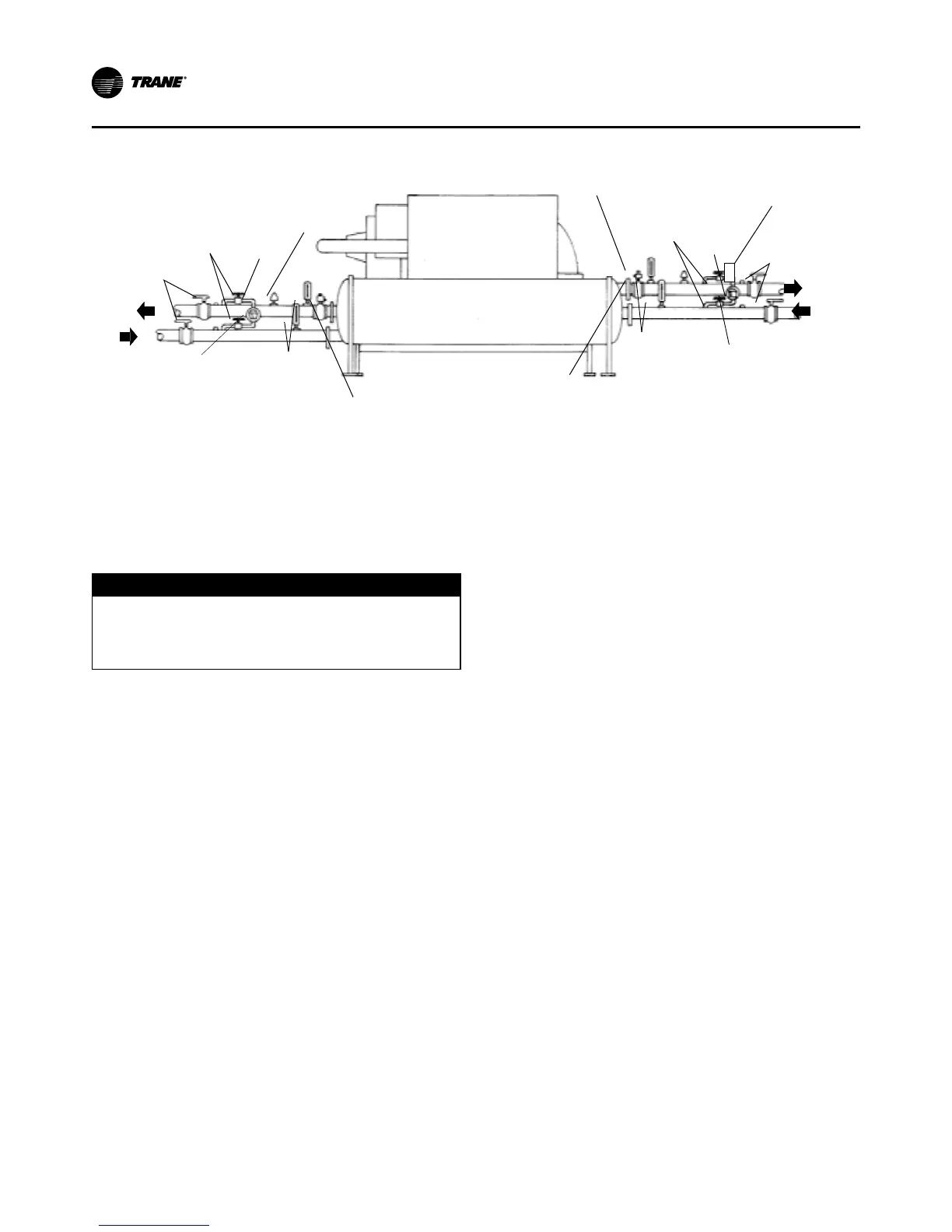
Flow
Shutoff
Valves
Reg. Valve (Opt.)
Cond Water
Flow Switch
Refer to Trane Engineering Bulletin - Series R
®
Chillers Sound Ratings and
Installation Guide for sound-sensitive applications.
Water Pressure Relief Valves
D
CAUTION
Shell Damage!
Install a pressure relief valve in both evaporator and
condenser water systems. Failure to do so may result
in shell damage.
Install a water pressure relief valve in one of the con-
denser and one of the evaporator water box drain con-
nections or on the shell side of any shutoff valve. Water
vessels with close-coupled shutoff valves have a high
potential for hydrostatic pressure buildup on a water
temperature increase. Refer to applicable codes for relief
valve installation guidelines.
Flow Sensing Devices
The installer must provide flow switches or differential
pressure switches with pump interlocks to sense sys-
tem water flow. Flow switch locations are schematically
shown in Figure 27.
To provide chiller protection, install and wire flow switch-
es in series with the water pump interlocks, for both
chilled water and condenser water circuits (refer to the
Installation Electrical section). Specific connections and
schematic wiring diagrams are shipped with the unit.
Flow switches must stop or prevent compressor oper-
ation if either system water flow drops off below the
required minimum shown on the pressure drop curves.
Follow the manufacturer’s recommendations for selec-
tion and installation procedures. General guidelines for
flow switch installation are outlined below.
• Mount the switch upright, with a minimum of 5 pipe
diameters straight, horizontal run on each side.
• Do not install close to elbows, orifices or valves.
Note: The arrow on the switch must point in the direc-
tion of the water flow.
• To prevent switch fluttering, remove all air from the
water system.
Note: The UC800 provides a 6-second time delay on the
flow switch input before shutting down the unit
on a loss-of-flow diagnostic. Contact a qualified
service organization if nuisance machine shut-
downs persist.
• Adjust the switch to open when water flow falls
below nominal. Refer to the General Data table in
Section 1 for minimum flow recommendations for
specific water pass arrangements. Flow switch con-
tacts are closed on proof of water flow.