Installation Mechanical
RTHD-SVX02H-EN 35
Unit Leveling
Note: The electrical panel side of the unit is designated
as the “front” of the unit.
1. Check unit level end-to-end by placing a level on the
top surface of the evaporator shell.
2. If there is insufficient surface available on the top of
the evaporator shell, attach a magnetic level to the
bottom of the shell to level the unit. The unit should
be level to within 1/4” (6.35 mm) over its length.
3. Place the level on the evaporator shell tube sheet
support to check sideto- side (front-to-back) level.
Adjust to within 1/4” (6.35 mm) of level frontto- back.
Note: The evaporator MUST be level for optimum heat
transfer and unit performance.
4. Use full-length shims to level the unit.
Water Piping
Piping Connections
D
CAUTION
Equipment Damage!
To prevent equipment damage, bypass the unit if using
an acidic ushing agent.
Make water piping connections to the evaporator and
condenser. Isolate and support piping to prevent stress
on the unit. Construct piping according to local and na-
tional codes. Insulate and flush piping before connecting
to unit.
Use grooved pipe connectors for all water piping con-
nections. Evaporator and condenser water inlet and
outlet sizes and locations are shown by the unit submit-
tals and in Figure 13 through Figure 18. The designation
in the tables corresponds to the compressor frame code
followed by the evaporator shell code followed by the
condenser shell code as given in the unit model number,
digits 6, 7, 14, 15, 21 and 22. Table 13 gives additional
water connection information.
Reversing Water Boxes
All water boxes may be reversed end-for-end. Do not
rotate water boxes. Remove the sensors from the wells
before removing the water box. Complete the water box
switch and replace the sensors. See Figure 13 through
Figure 18 for correct orientation of the water inlet and
outlet.
If the water boxes are reversed, be sure to properly re-
wire the water temperature sensors in the control panel.
Note: Be certain to replace water boxes right-side-up
to maintain proper baffle orientation. Use new
o-rings.
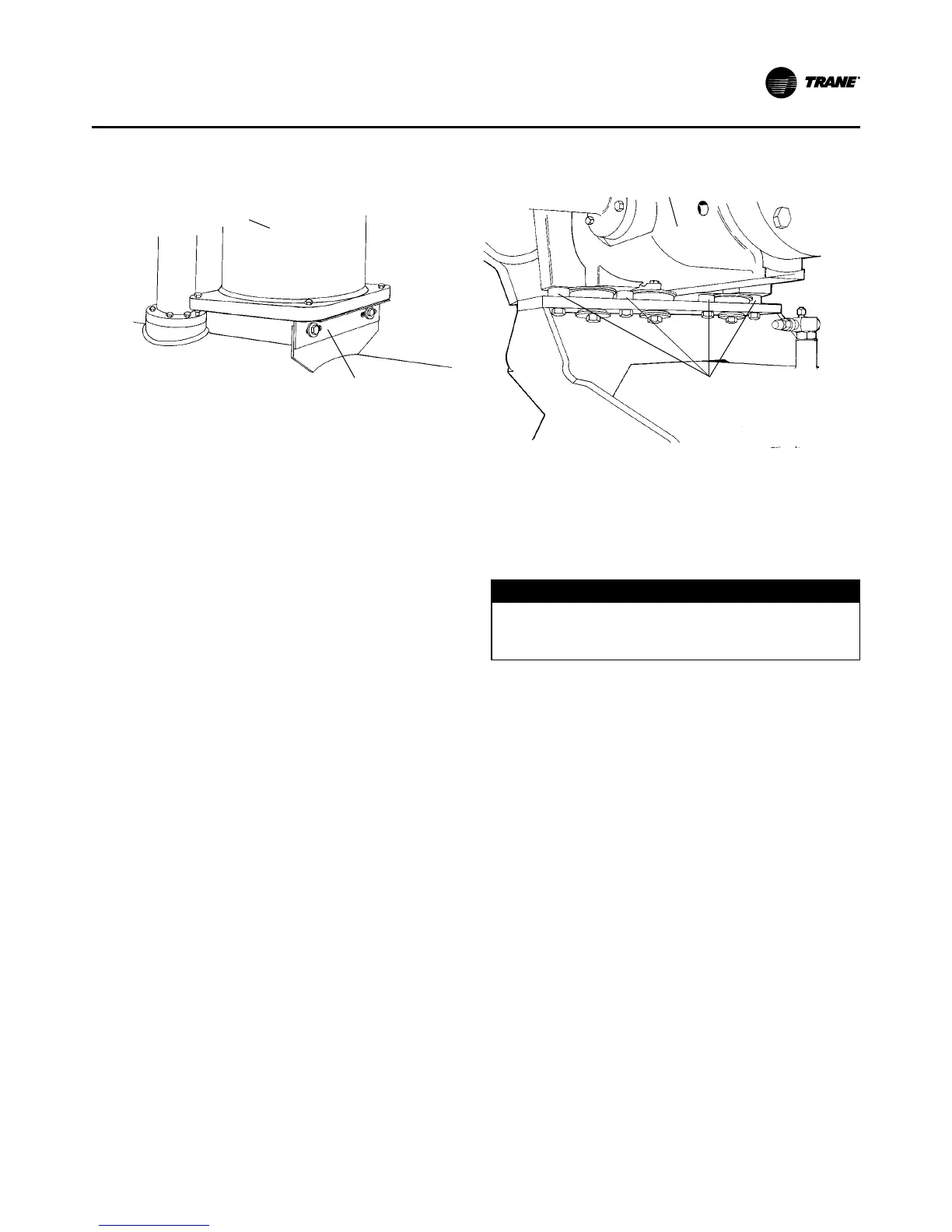
Figure 12. Oil Separator with Shipping Bracket and Compressor Shipping Spacer
Shipping Bracket
Oil Separator
Remove 4 Shipping
Spacers (only 3 on B