74 RTHD-SVX02H-EN
Operating Principles Mechanical
This section contains an overview of the operation and
maintenance of Series R chillers equipped with micro-
computer-based control systems. It describes the overall
operating principles of the RTHD water chiller.
Following the section is information regarding specif-
ic operating instructions, detailed descriptions of the
unit controls and options (Operator Interface - Control
Systems), and maintenance procedures that must be
performed regularly to keep the unit in top condition
(Periodic Maintenance and Maintenance Procedures).
Diagnostic information (Diagnostics) is provided to allow
the operator to identify system malfunctions.
Note: To ensure proper diagnosis and repair, contact a
qualified service organization if a problem should
occur.
General
The Model RTHD units are single-compressor wa-
ter-cooled liquid chillers. These units are equipped with
unit-mounted starter/control panels.
The basic components of an RTHD unit are:
• Unit-mounted panel containing UC800 controller and
Input/Output LLIDS
• Helical-rotary compressor
• Evaporator
• Electronic expansion valve
• Water-cooled condenser with integral subcooler
• Oil supply system
• Oil cooler (application dependent)
• Related interconnecting piping.
Refrigeration (Cooling) Cycle
The refrigeration cycle of the Series R chiller is concep-
tually similar to that of other Trane chiller products. It
makes use of a shell-and-tube evaporator design with re-
frigerant evaporating on the shell side and water flowing
inside tubes having enhanced surfaces.
The compressor is a twin-rotor helical rotary type. It uses
a suction gascooled motor that operates at lower motor
temperatures under continuous full and part load operat-
ing conditions. An oil management system provides an
almost oil-free refrigerant to the shells to maximize heat
transfer performance, while providing lubrication and
rotor sealing to the compressor. The lubrication system
ensures long compressor life and contributes to quiet
operation.
Condensing is accomplished in a shell-and-tube heat
exchanger where refrigerant is condensed on the shell
side and water flows internally in the tubes.
Refrigerant is metered through the flow system using an
electronic expansion valve, that maximizes chiller effi-
ciency at part load.
A unit-mounted starter and control panel is provided on
every chiller. Microprocessor- based unit control mod-
ules (UC800) provide for accurate chilled water control as
well as monitoring, protection and adaptive limit func-
tions. The “adaptive” nature of the controls intelligently
prevents the chiller from operating outside of its limits,
or compensates for unusual operating conditions, while
keeping the chiller running rather than simply tripping
due to a safety concern. When problems do occur, diag-
nostic messages assist the operator in troubleshooting.
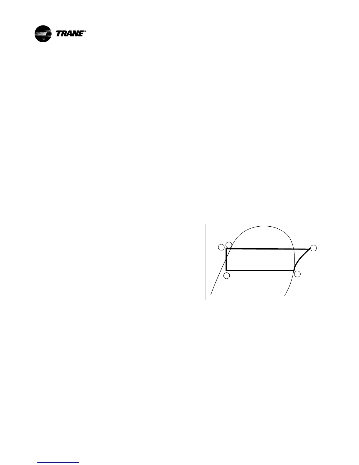
Cycle Description
The refrigeration cycle for the RTHD chiller can be de-
scribed using the pressure- enthalpy diagram shown in
Figure 36 Key State Points are indicated on the figure
and are referenced in the discussion following. A sche-
matic of the system showing the refrigerant flow loop as
well as the lubricant flow loop is shown in Figure 37.
Figure 36. Pressure /Enthalpy Curve
Pressure
Enthalpy
Liquid
Gas
1
2
3
4
5
Evaporation of refrigerant occurs in the evaporator. A
metered amount of refrigerant liquid enters a distribu-
tion system in the evaporator shell and is then distribut-
ed to the tubes in the evaporator tube bundle. The refrig-
erant vaporizes as it cools the water flowing through the
evaporator tubes. Refrigerant vapor leaves the evapora-
tor as saturated vapor (State Pt. 1).
The refrigerant vapor generated in the evaporator flows
to the suction end of the compressor where it enters the
motor compartment of the suction-gascooled motor.
The refrigerant flows across the motor, providing the
necessary cooling, then enters the compression cham-
ber. Refrigerant is compressed in the compressor to
discharge pressure conditions. Simultaneously, lubricant
is injected into the compressor for two purposes: (1) to
lubricate the rolling element bearings, and (2) to seal the
very small clearances between the compressor’s twin
rotors. Immediately following the compression process