S9V2
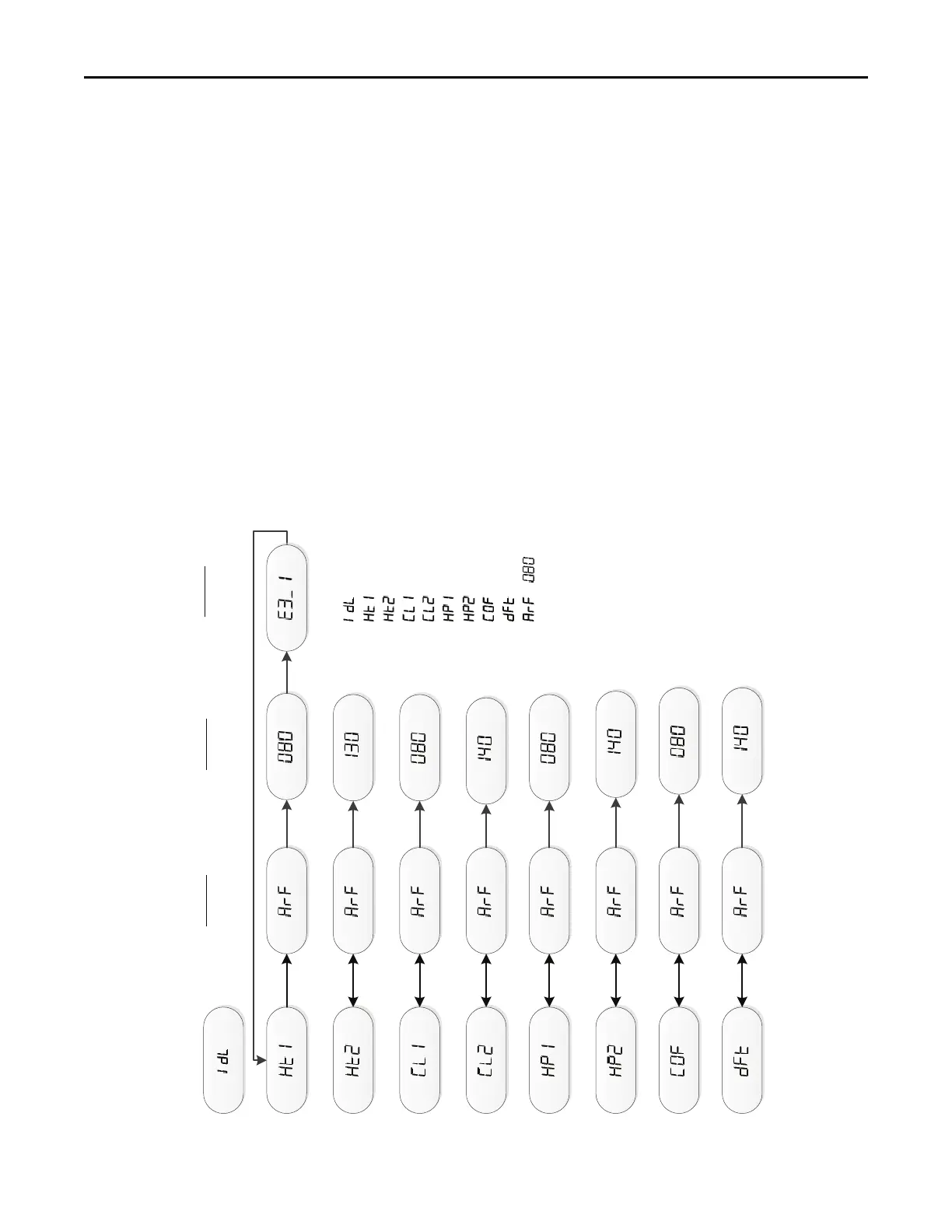
Examples of System Status
= Idle, no demand for cooling, hea!ng, or fan
= Demand for 1
st
stage gas heat
= Demand for 2
nd
stage gas heat
= Demand for 1
st
stage cooling
= Demand for 2
nd
stage cooling
= Demand for 1
st
stage heat pump
= Demand for 2
nd
stage heat pump
= Demand for con!nuous fan
= Demand for outdoor unit defrost, furnace running in gas heat mode
/ = Calculated Airflow is 800 CFM.
Airflow display is rounded down to the nearest 10 cfm
NOTES:
(1) The menu status displayed is solely dependent on the input of 24VAC
that is applied to the low voltage terminal strip.
(2) The status will alternate between the system mode and the airflow
request every 2 seconds.
(3) If an error occurs, an E*.* will alternately flash with the system mode
and airflow request. See first example
(4)
Mul!ply the value shown by 10 for actual airflow
Example
800 CFM
Example
1st Stage Pressure
Switch Error
Example
Calculated Airflow

 Loading...


