10
S9XB-SVX001-1D-EN
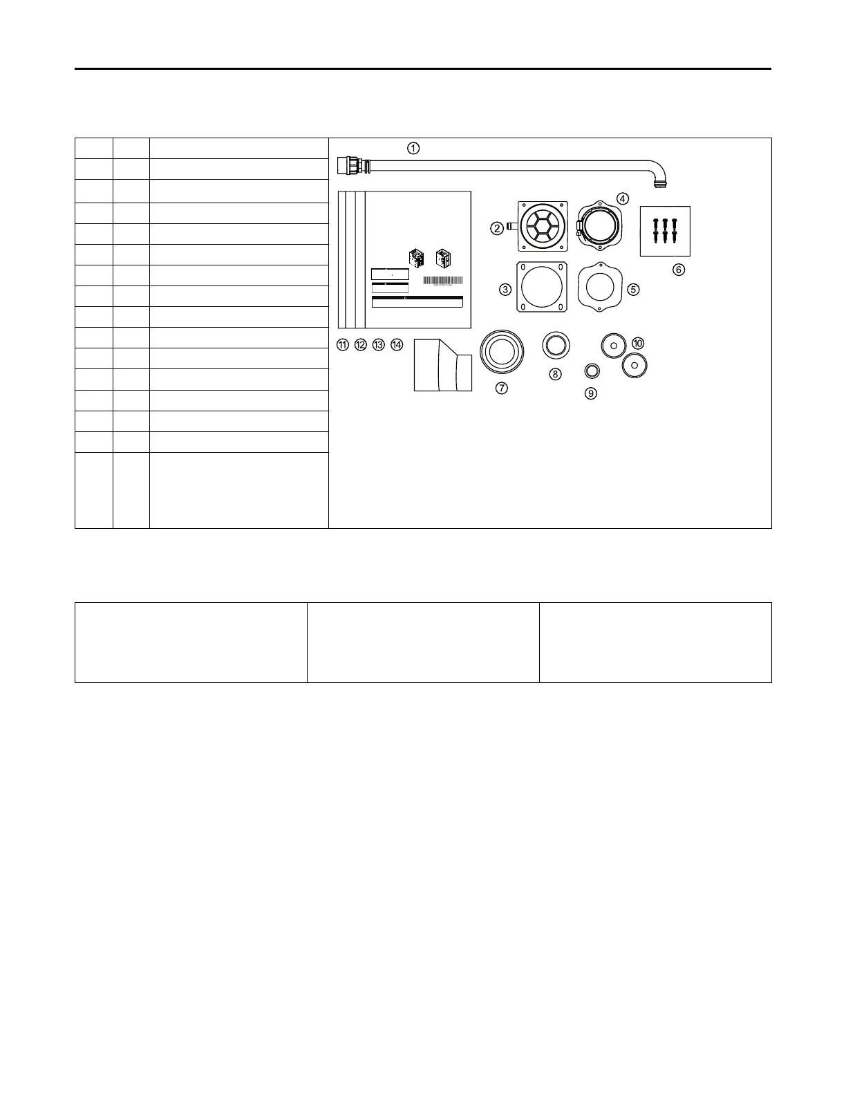
Document Pack Contents
Item
Qty. Description
SSAAFFEETTYY WWAARRNNIINNGG
Onlyqualied personnelshould installand servicethe equipment.The installation,startingup, andservicing ofheating, ventilating,and air-conditioning
equipmentcan behazardous andrequires specicknowledge andtraining. Improperlyinstalled,adjusted oraltered equipmentby anunqualied person
couldresult indeath orseriousinjury. Whenworking onthe equipment,observe allprecautions inthe literatureand onthe tags,stickers, andlabels that
areattached tothe equipment.
Upow/Horizontal and Dedicated Downow
Gas-Fired, Direct/Non-Direct Vent, Single Stage / Two Stage
Condensing Furnaces with High Efciency Motor
NNoottee::Grap
hics
i
n
t
his
d
ocument
a
re
f
or
r
epresentation
only. Actual model may differ in appearance.
CAUTION
!
COILREQUIREMENT!
Failureto followthisCautioncould resultinproperty damageorpersonalinjury. 4GXC*and
4MXC*coils installedonupflowfurnaces invertical,horizontalleft, orhorizontalright
orientationswithouta factoryinstalledmetal drainpanshieldmust useaMAY*FERCOLKITAA
kit.Coils installedonupflowfurnaces musthavedrain pansthatare suitablefor 400°F
(205°C)or haveametal drainpanshield.Downflow furnacesdonot requireametaldrain pan
shieldor theuseof theMAY*FERCOLKITAAkit.
Installation, Operation, and Maintenance
UUppffllooww,,CCoonnvveerrttiibbllee ttoo
HHoorriizzoonnttaall LLeefftt aanndd HHoorriizzoonnttaall
LLeefftt DDeeddiiccaatteedd DDoowwnnffllooww
S9X1
S
9X2
S9B1
WARNING
FIRE HAZARD!
Failureto follow thisWarning could result in property damage, severepersonal
injury,or death.
This Warningappliesto installations with a ammablerefrigerationsystem.
The furnacemust be powered except for service.The furnace shall be installed
and connectedaccording to installation instructions and wiring diagrams that
areprovided with the evaporator coil.
June
2024
SS99XXBB--SSVVXX000011--11 --EENND
1 1
Condensate Drain Tube Assembly
2 1
Inlet Vent (2"- ADP01586 and 3" -
ADP01587)
(a)
3 1 Inlet Vent Gasket
4 1
Outlet Vent Assembly
5 1 Outlet Vent Gasket
6 6 Screws
7 1
Condensate Trap Grommet
8 1
Plug — Condensate/Gas
9 1
Plug — Electrical
10 2
Grommet — Condensate/Gas
11 1
Installation, Operation, and
Maintenance
12 1 Owner Guide
13 1
Limited Warranty
14 1
2” to 3” Coupling — CPL01544
(b)
6 2
S9B1/S9X1 Tinnerman Clips (not
pictured)
Note: Tinnerman Clips should be
kept with unit and are used
if the door panel flange hole
(s) becomes stripped.
(a)
3” inlet vent supplied with S9X1D120U, S9X1D120D, S9X2D120U, S9X2D120D, S9B1D120U, and S9B1D120D only. 2” inlet vent supplied with all other
models.
(b)
Supplied with S9X1D120U, S9X1D120D, S9X2D120U, S9X2D120D, S9B1D120U, and S9B1D120D only
Part List
• Igniter
• Flame Sensor
• In-shot Burner(s)
• Gas Valve
• Inducer Assembly
• Blower Motor
• Blower Wheel
• IFC (Integrated Furnace Control)
• Pressure Switch(es)
• Main Thermal Limit
• Roll-Out Switch(es)
• Reverse Air Switch(es)
AAcccceessssoorriieess