82
S9XB-SVX001-1D-EN
23. Connect PS2 tubing to switch and new sensing
location.
IImmppoorrttaanntt:: Cut to length but insure there is a rise in the
tubing to avoid condensed flue gases from
entering pressure switch.
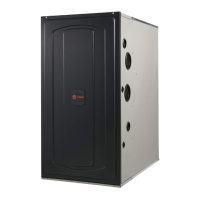
24. Remove port cap on left side of inducer and connect
inducer condensate tubing. Connect other end of
inducer condensate tubing to top port on the
condensate trap. Cut tubing to length, if necessary.
25. Install previously removed port cap onto bottom
port of the inducer. (As viewed in upflow)
26. Connect condensate pressure switch tubing to
pressure port on the condensate trap.
IImmppoorrttaanntt:: Trim the PS2 pressure switch tubing to
length to ensure there is no sag or trap
created.
27. Remove port plug from rain gutter and install in
new position on opposite side of the rain gutter.
28. Connect rain gutter condensate hose to the rain
gutter and the lower port of the condensate trap.
Route rain gutter condensate hose to the right of
the inducer motor.
Furnace in Horizontal Right
Position - Top Vented
Combustion Air
Changes need to be made to the inducer orientation
when installing the upflow furnace in the horizontal
right position with the combustion air vented through
the left side. Additional changes are needed for hose
routing, condensate trap location, and inducer port
caps, and the condensate plug.
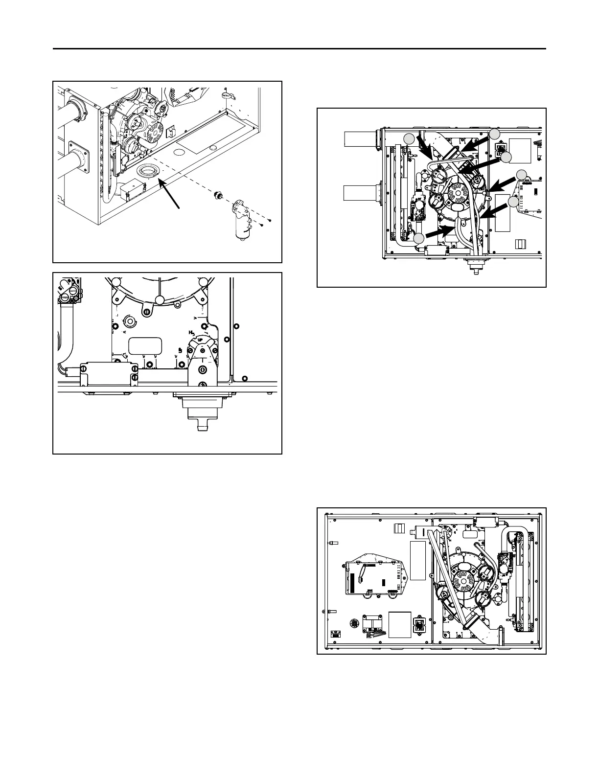
The figure below shows the furnace as it is sent from
the factory.
Use the following steps to modify the furnace for
horizontal right with left side venting of combustion air.
IImmppoorrttaanntt:: PS2 conversion does not apply to the S9X1
or S9B1 models.
Before proceeding, lay unit on its back to make the
conversion easier.
1. Remove all drain hoses from condensate trap.
FFuurrnnaaccee CCoommbbuussttiioonn AAiirr EExxhhaauusstt OOppttiioonnss