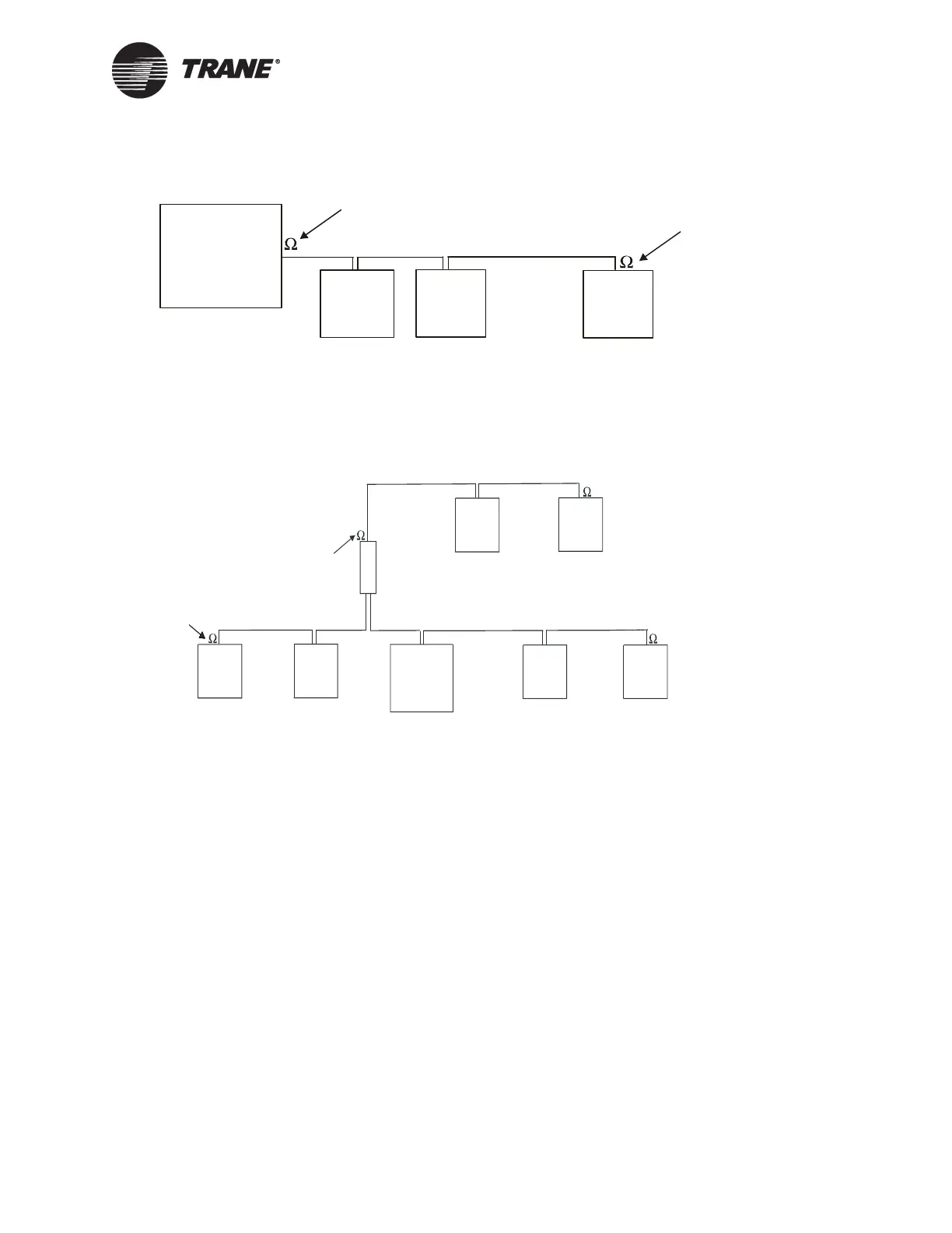
Termination resistance placement for Comm5 links
CNT-SVN01C-EN 43
Figure 23. Daisy chain resistor placement
Figure 24. Alternate daisy chain resistor placement
Termination resistor
Termination
resistor
System panel
Device
Device
Device
Figure Note:
• 105 Ω, 1%, 1/4 Watt for 22 AWG, Level 4
• 82 Ω, 1%, 1/4 Watt for 18 AWG, Trane “purple’ wire
Repeater
Termination
resistor
Termination
resistor
Termination
resistor
Termin at ion
resistor
Device Device
Device
Device
System panel
Device
Device
Figure Note:
• Maximum wire length for the entire configuration Comm5 is 4,500 ft (1,400 m)
• Maximum wire length for Comm5 is 4,500 ft (1,400 m) (Comm5 wire length
limitations can be extended through the use of a link repeater, see “Comm5
physical link repeater” on page 44)

 Loading...


