Comm5 physical link repeater
CNT-SVN01C-EN 45
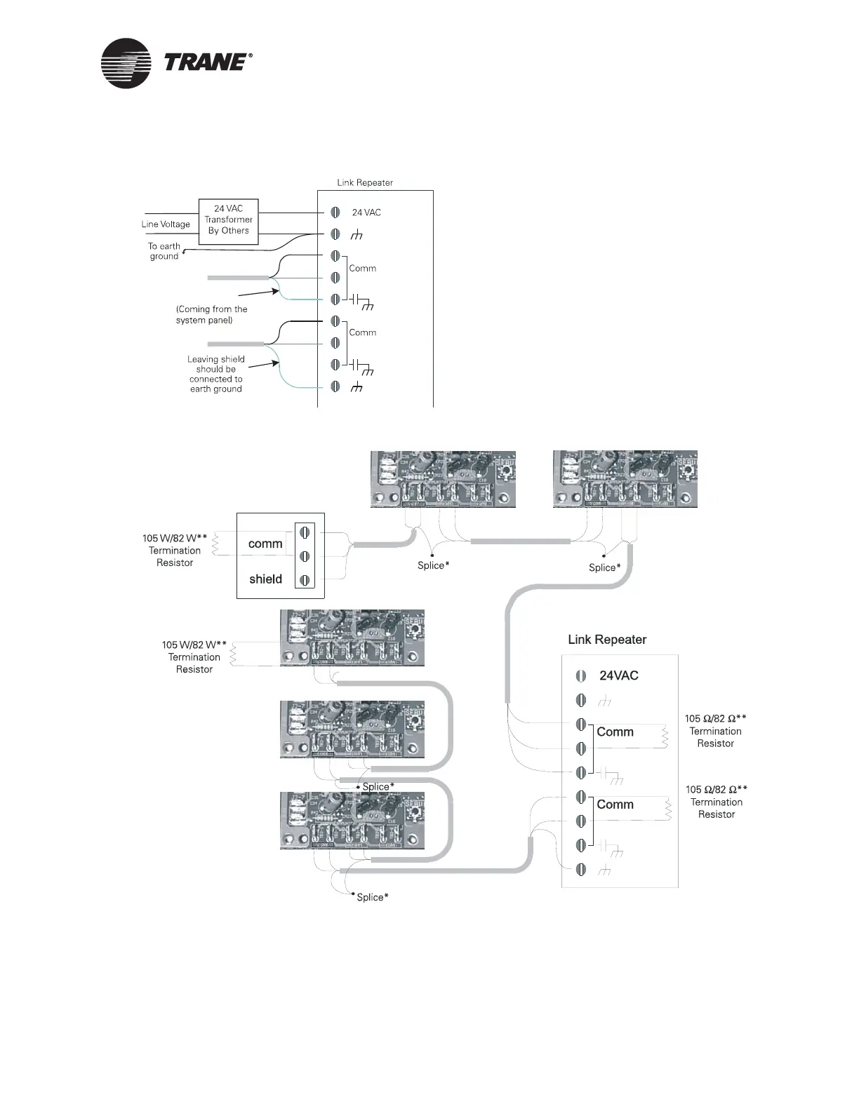
Figure 25. Comm5 shield repeater connection
Figure 26. Comm5 daisy chain repeater connection and shielded wire
Entering shield
System Panel
* A continuous shield is required
when shielded wire is used. If unshielded communication wire is used, no shield connections are
necessary. At each controller, splice shield wire and tape back to prevent grounding. Connect shield
wire to earth ground at system panel and repeater.
**The value of the termination resistor is dependent on the wire type: 105-ohm for 22 AWG, Level 4
wire and 82-ohm for 18 AWG, Trane “purple” wire.

 Loading...


