RLC-
VU006A-E
1
The following equations apply for EDLS:
Volta
e Si
na
Current Si
nal
As
enerated from
external sourc
VDC+0.133*
%
-6.
mA=0.266*
%
-12.
As processed by
C
%=7.5*(VDC)+45.
%=3.75*(mA)+45.
If the EDLS input develops an open or short, the LLID
will report either a very high or very low value bac
to
the man processor. This will generate an in
ormational
diagnostic and the unit will de
ault to using the Front
Panel
Tracer TD7
Current Limit Setpoint
The Tracer™ TU
ervice T
l must be used t
set the
input si
nal type
rom the
actory de
ault o
2-10 VDC to
that
4-20 mA current. Tracer TU must be als
be used
to install or remove the External Demand Limit
etpoint
O
tion for fi eld installation, or can be used to enable or
disable the feature
if installed
.
EDL
and ECW
Analo
Input
i
nal Wirin
Details
Both the ECW
and EDL
can be connected and setup
as either a 2-10 VDC (factor
default), 4-20 mA, or
resistance input
also a form of 4-2OmA
as indicated
elow.
ependin
on the type to
e used, the
racer
ervice Tool must be used to confi
ure the LLID and the
MP for the proper input type that is bein
used. This is
accomplished by a setting change on the Custom Tab o
the Confi
uration View within Tracer TU.
For proper unit operation, BOTH the EDLS
nd ECW
settin
s MU
T be the sam
2-10 VDC or 4-20mA), even if only on
nput is to
e used.
he
2-3 and
2-6 terminal is chassis grounded and
terminal J2- 1 and J2-4 can be used to source 12 VD
.
The ECL
uses terminals J2-2 and J2-
. ECW
uses
terminals
2-5 and
2-6.
oth inputs are only compati
le
with high-side current sources.
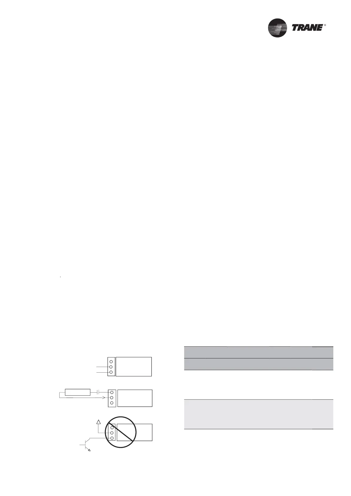
Figure 2. Wiring examples for EDLS and ECWS
J2-1 & 4 Dual
J2-2 & 5 Analog
J2-3 & 6 I/O LLID
J2-1 & 4 Dual
J2-2 & 5 Analog
J2-3 & 6 I/O LLID
J2-1 & 4 Dual
J2-2 & 5 Analog
J2-3 & 6 I/O LLID
Resister
2-10 VDC, 4-20mA
I = 20/(R + 200)
I
Chilled Water Reset (CWR
C800 resets the chilled water tem
erature set
oint
based on either return water tem
erature, or outdoor air
tem
erature. Return Reset is standard, Outdoor Reset is
optional.
The following shall be selectable:
ne of three Reset Types: None, Return Water
Temperature Reset,
utdoor Air Temperature Reset, or
onstant Return Water Temperature Reset.
Reset Ratio Set Points
For outdoor air tem
erature reset there shall be both
ositive and ne
ative reset ratio’s
Start Reset Set Points
Maximum Reset
et Points.
The equations
or each type o
reset are as
ollows:
eturn
CWS’ = CWS + RATIO
START RESET -
TWE - TWL
nd CW
’ > or = CW
nd CW
’ - CW
< or = Maximum Reset
utd
r
CWS’ = CWS + RATIO *
START RESET - TOD
nd CW
’ >
r = CW
nd CW
’ - CW
< or = Maximum Reset
wh
r
CWS’ is the new chilled water set point or the “reset
CW
”
CW
is the active chilled water set
oint before any reset
as occurred, e.g. normally Front Panel, Tracer, or ECW
RESET RATI
is a user adjustable gain
TART RE
ET is a user adjustable reference
T
D is the outdoor temperature
TWE is enterin
evap. water temperature
is leaving evap. water temperature
MAXIMUM RESET is a user adjustable limit providing
the maximum amount of reset. For all types of reset,
CW
’ - CW
<
r = Maximum Reset.
an
ncrement
e
et
e
e
et
ati
tart
e
et
ax
e
et
IP
nit
SI
nit
actor
efa
lt
et
rn
t
%
t
t
F
%
%
%
2.2 to
6.7 C
0.0 to
1.1 C
t
r
0 to
80%
t
F
t
F
%
%
%
10 to
54.4 C
0.0 to
1.1 C
nstallation El
ctrical

 Loading...


