RLC-
VU006A-E4
nstallation El
ctrical
Motor Cable
The motor must be connected to terminals U/T1/96, V/
T2/97, W/T3/98. Earth (ground) to terminal 99. All types o
three-
hase asynchronous standard motors can be used
with a frequency converter unit. The factory setting is for
clockwise rotation with the
requency converter output
c
nnected as f
ll
ws:
Terminal n
.
uncti
96, 97, 98, 99
ains U/T1, V/T2, W/T3
arth (
round)
Motor Rotation Ch
c
The direction of rotation can be chan
ed by switchin
two phases in the motor cable or by chan
in
the settin
of 4-10 Motor
eed Direction.
A motor rotation check can be performed using1-28
Motor Rotation Check and
ollowing the steps shown in
t
e
isp
ay
A
Mains
onn
ctio
Size wirin
is based upon the input current of the
re
uency converter
Comply with local and national electrical codes for
c
le size
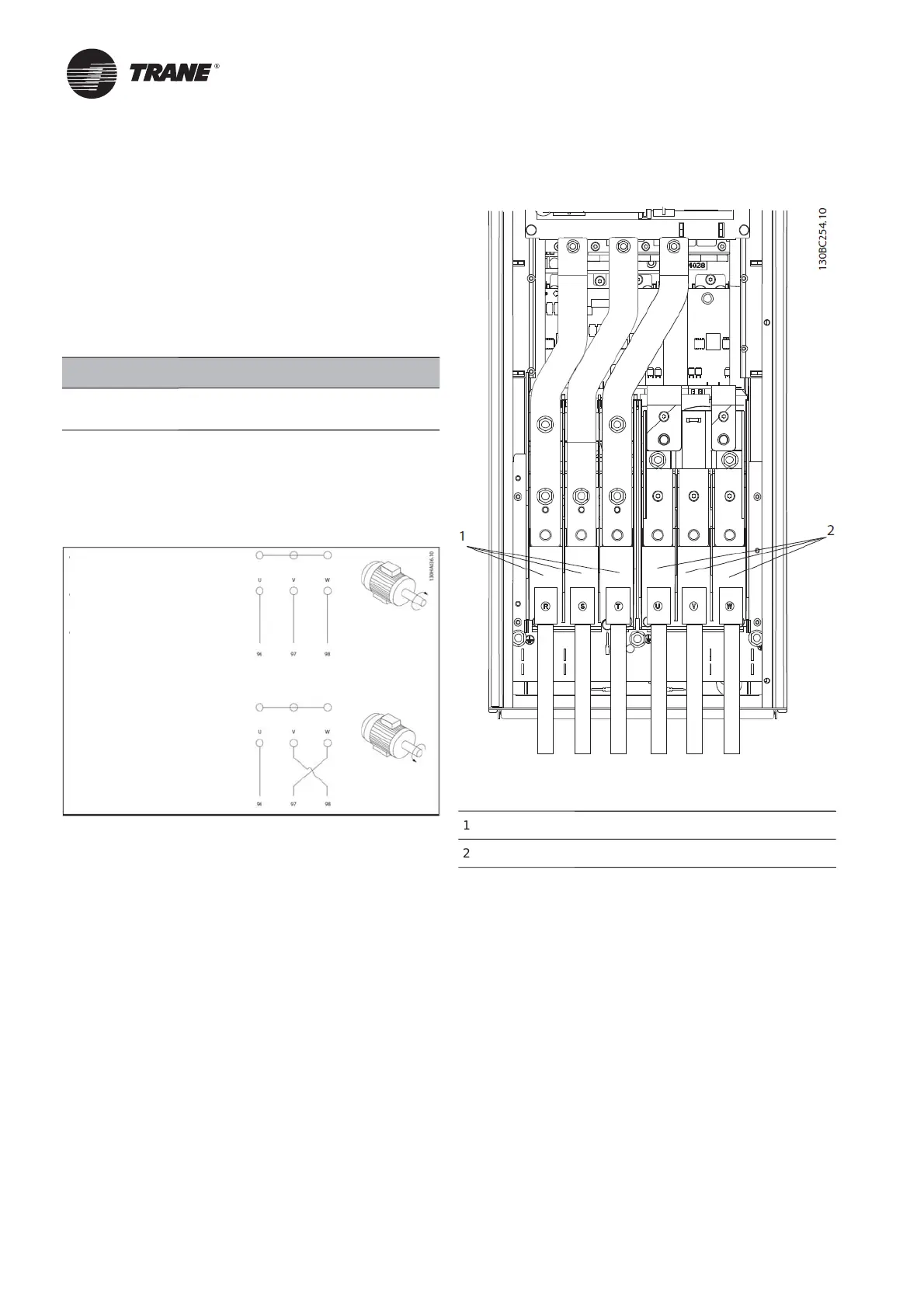
onnect 3-phase A
input power wirin
to terminals
L1, L2, and L3
see Figure 1
Figure 1. Connecting to AC Mains
Mains c
nnecti
n
otor connection
Earth
ground
the cable in accordance with the
instructions provided
All
requency converters may be used with an isolated
input source as well as with earth
round
reference
ower lines. When su
lied from an isolated mains
source
IT mains or fl oating delta
or TT/TN-S mains
ith a grounded leg
grounded delta
, set 14-50 RFI
Filter t
FF
When off, the internal RFI fi lter capacitors between
the chassis and the intermediate circuit are isolated to
avoi
amage to t
e interme
iate circuit an
to re
uce
earth (ground) capacity currents in accordance with
IE
61800-3.
erminal
/
1/96
connected to
-
hase
Termin
l V
T2
7
connected to
-
hase
Terminal W/T
/98
connected to
-
hase

 Loading...


