RLC-
VU006A-E4
1
ntr
l
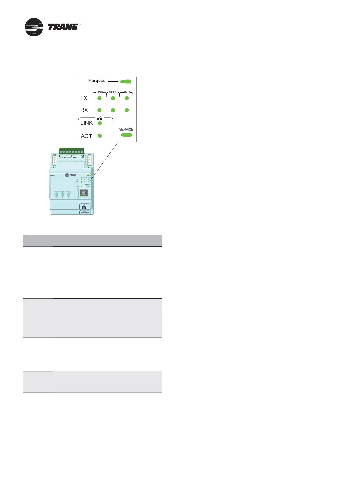
C800 Statu
ar
uee
wered. If the Marquee LED is
reen solid,
the UC800 is
owered and no
roblems exist.
ow
ower or malfunction
If the Mar
uee
ED is red solid, the UC800 is
owered, but
there are
roblems
resent.
larm. The Mar
uee LED blinks Red when an
l
rm exists.
,
BU
, IM
Th
LED blinks
reen at the data transfer
rate when the UC800 transfers data to other
evices
n the link.
Th
LED blinks
ellow at the data transfer
rate when the UC800 receives data from
ther
evices
n the link.
th
rn
t
ink
Th
LED is solid
reen if the Ethernet
link is connected and communicatin
.
Th
CT LED blinks
ellow at the data
tr
nsfer r
te when
t
fl
w is
ctive
n the
link.
ervice
The Service LED is solid
reen when pressed.
or
ualifi ed service technicians onl
. Do not
s
.
NOTICE
ectrica
oise
Maintain at least 6 inches between low-volta
e (<30V)
and high voltage circuits. Failure to do so could result in
e
ectrica
noise that cou
d distort the signa
s carried by
the low-volta
e wirin
, includin
IPC.
Tracer TD7 Operator Interfac
nformation is tailored to o
erators, service technicians,
nd owners
hen operatin
a chiller, there is specifi c information
you need on a day-to-day basis—setpoints, limits,
iagnostic information, and reports.
ay-to-day operational information is presented at the
isplay. Logically organized groups of information—
chiller modes o
operation, active diagnostics, settings
nd reports put in
ormation conveniently at your
ngertips
Tr a c
r™ T
The RTHD o
erator interface allows for daily o
erational
as
s and setpoint chan
es. However, to adequately
service chillers
racer
service tool is re
uired.
(Non-Trane
ersonnel, contact your local Trane offi ce
for software
urchase information.) Tracer TU adds a
level of so
histication that im
roves service technician
effectiveness and minimizes chiller d
wntime. This
ortable PC-based service-tool software su
orts service
nd maintenance tasks, and is required
or so
tware
up
rades, confi
uration chan
es and major service
s
s
Tracer TU serves as a common interface to all Trane
chillers, and will customize itself based on the properties
of the chiller with which it is communicating. Thus, the
service technician learns only one service interface.
he panel
us is easy to trou
leshoot usin
sensor
verifi cation.
nly the defective device is replaced. Tracer
can communicate with individual devices or
roups
f devices.
All chiller status, machine con
guration settings,
customiza
le limits, and up to 100 active or historic
iagnostics are displayed through the service-tool
s
tware inter
ace.
s and their respective
racer
indicators visually
con
rm the availability o
each connected sensor, relay,
nd actuat
r.
racer
is designed to run on a customer
s laptop,
connected to the Tracer control
anel with a USB cable.
Your laptop must meet the
ollowin
hardware and
so
tware requirements:
1 GB RAM
minimum
1024 x 768 screen res
uti
CD-R
M driv
Ethernet 10
100 LAN c
rd
An available U
B 2.0
ort
Microsoft® Windows® XP Professional operation
system with Service Pack 3 (SP3) or Windows 7
Enterprise or Professional operatin
system (32-bit or
64-bit)
Microso
t .NET Framework 4.0 or later

 Loading...


