RLC-
VU006A-E
3
Overvie
THD units utilize the following control/interface
com
onents:
racer™ UC800 Controlle
racer TD7
perator Interfac
UC800
peci
cations
This section covers in
ormation pertaining to the UC800
c
ntr
ller hardware.
W
r
n
an
Port Descr
pt
on
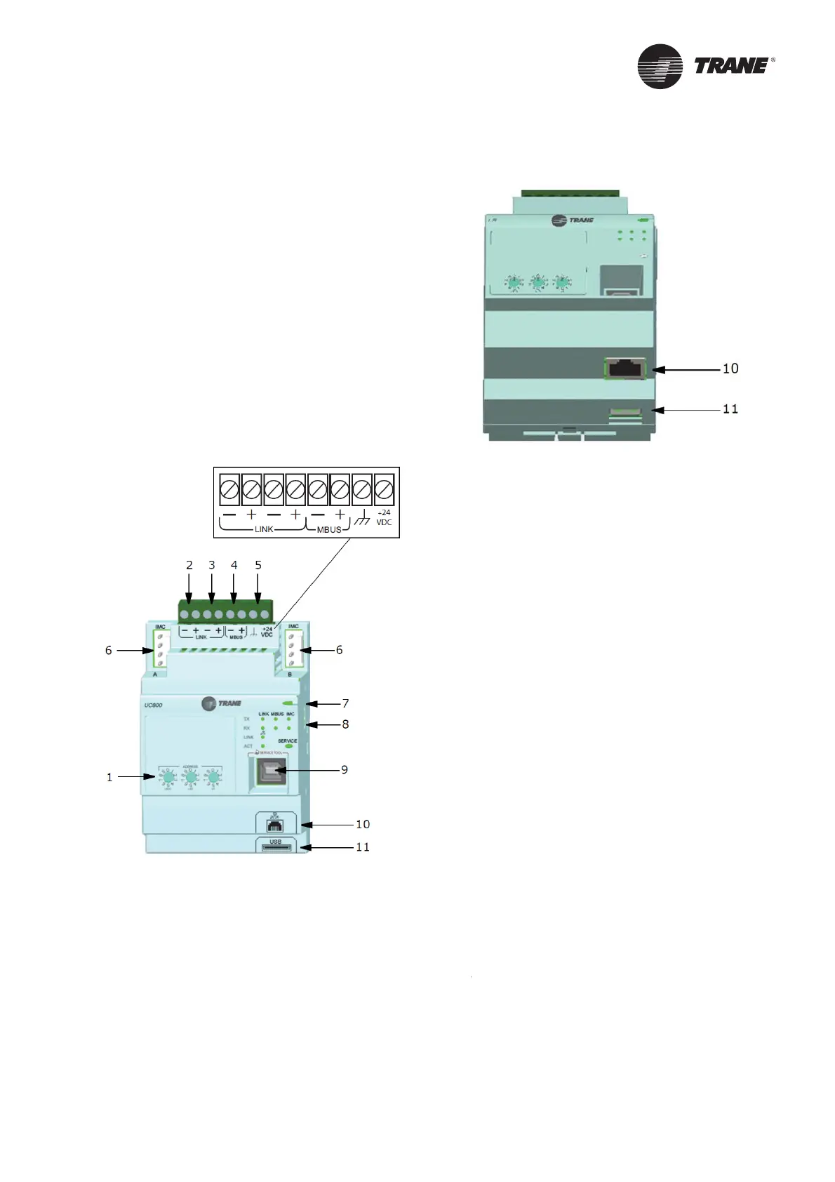
Figure 3 illustrates the U
800 controller ports, LEDs,
rotary switches, and wiring terminals. The numbered list
ollowing Figure 3 corresponds to the numbered callouts
in the illustrati
n.
Figure 3. Wiring locations and connection ports
ront
ie
Figure 3. Wiring locations and connection ports
ottom
iew
. Rotary Switches for settin
BACnet® MAC address or MODBUS ID
. LINK for BACnet MS/TP, or MODBUS Slave
two terminals, ±
. Field
wir
d if us
d
3. LINK for BACnet MS/TP, or MODBUS Slave (two terminals, ±). Field
wired if used
4. Machine bus for existin
machine LLIDs (IPC3 Tracer bus 19.200 baud).
IPC3 Bus: used for Comm4 using TCI or LonTalk® using LCI-C
5. Power (210 mA at 24 Vdc) and
round terminations (same bus as
tem 4). Factor
wired
.
ot used
. Marquee LED power and UC800 Status indicator.
.
tatus LEDs for the BA
link, MBus link, and IMC link
9. USB device ty
e B connection for the service tool (Tracer TU)
0. The Ethernet connection can only be used with the Tracer Ada
tiView
is
ay
1. USB Host (not used)
Communication Interfaces
There are
our connections on the UC800 that support
the communication interfaces listed. Refer to Fi
ure 3,
. 13
or the locations o
each o
these ports.
BACnet M
/T
M
DBU
lave
onTalk using LCI-C
from the IPC3 bus
Comm 4 using TCI
from the IPC3 bus
Rotary Switche
There are three rotary switches on the
ront o
the UC800
controller. Use these switches to de
ne a three-digit
ddress when the UC800 is installed in a BACnet
r
MODBUS system (e.g., 107, 127, etc.)
Valid addresses are 001 to 127 for BACnet and 001
o 247 for M
DBUS.
ED Description and
peration
There are 10 LEDs on the
ront o
the UC800. Figure 4
hows the locations of each LED and Table 8, p. 14
escribes their behavior in specifi c instances
ntr
ls

 Loading...


