VAV-SVX07F-EN 17
Wiring Installation
BACnet MS/TP Communication Link
This subsection provides information about:
• “Wiring Guidelines”
• “Wiring Best Practices,” p. 18
• “Setting Up the UC400 Controller on a BA
Cnet Link,” p. 19
• “Setting the Address,” p. 19
• “BACnet Networks Without a Tracer SC Sy
stem Controller,” p. 20
• “BACnet Ne
tworks With a Tracer SC System Controller,” p. 20
• “Wiring Requirements,” p. 21
• “Connecting the Wires,” p. 21
• “Application Wiring,” p. 22
For more details about BACnet MS/TP co
mmunicati
on link, refer to the BACnet MS-TP Wiring and
Link Performance Best Practices and Troubleshooting Guide (BAS-SVX51).
WARNING
Electrocution and Fire Hazards with Improperly Installed and Grounded
Field Wiring!
Improperly installed/grounded field wiring poses FIRE & ELECTROCUTION hazards. To avoid
these hazards, the user MUST follow requirements for field wiring installation and grounding
as described in NEC and local/state electrical codes. All field wiring MUST be performed by
qualified personnel. Failure to follow these requirements could result in death or serious injury.
Wiring Guidelines
• Use 18 AWG Trane purple-shielded communication wire for BACnet installations.
• Link limit of 4,000 ft and 60 devices maximum (without a
repeater).
• Use a Trane BACnet termination
on each end of the link.
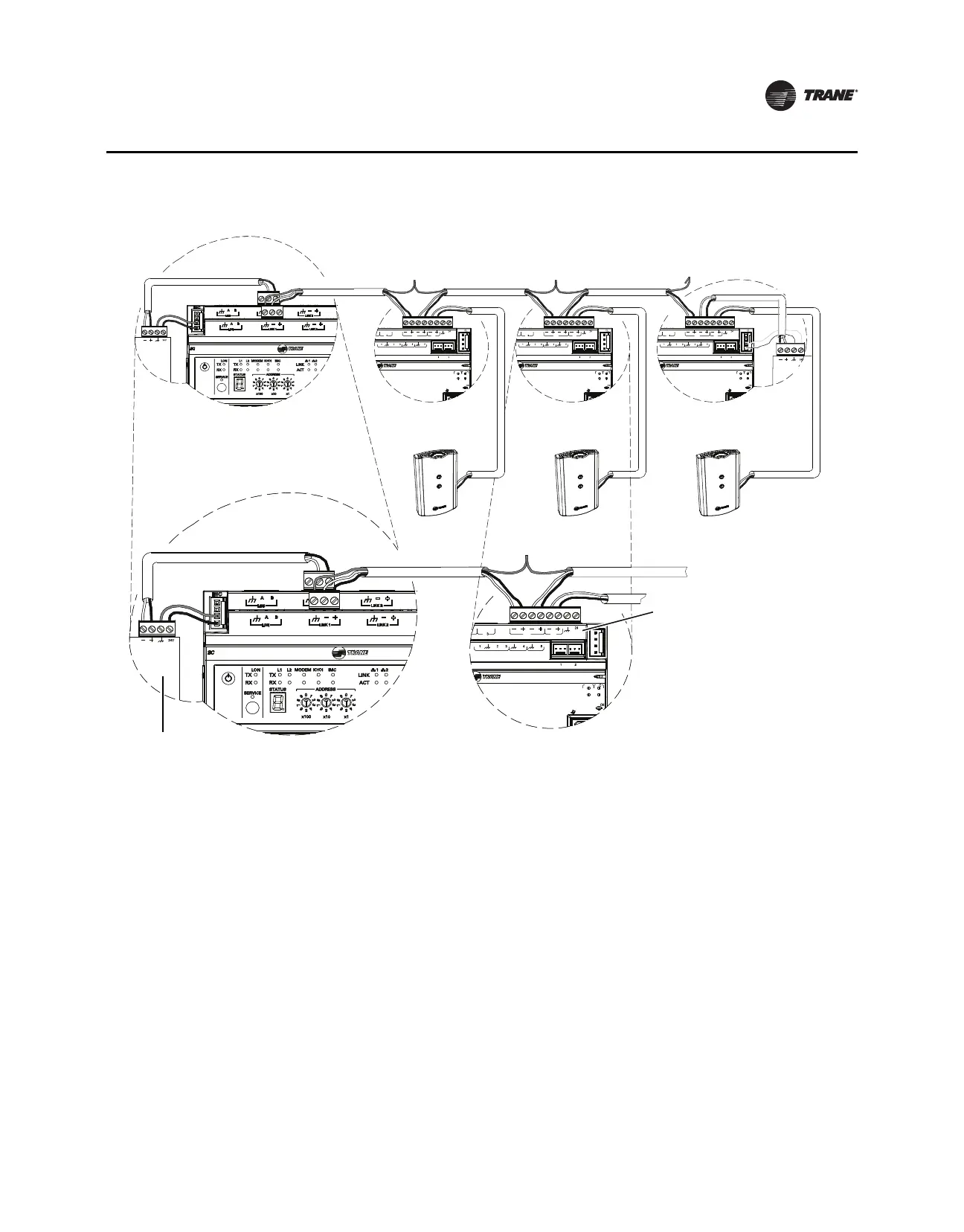
• Use daisy chain topology (refer to Figure 1, p. 18).
• Maintain polarity.

 Loading...


